HYDRAULIC SYSTEM
6-71TX525 Service Manual Rev. 000
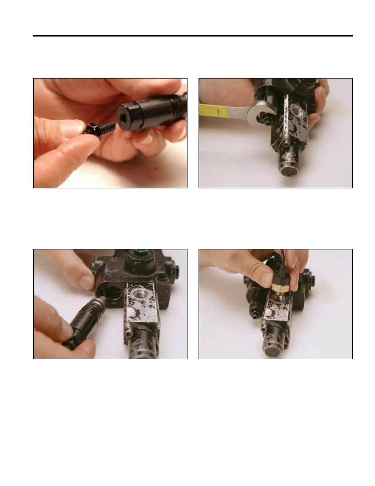
26. Thread the adjusting screw and nut into the top of
the relief body (Fig. 1100).
28. Tighten the relief assembly using a 19mm wrench
(Fig. 1102).
Fig 1100 PICT-2752
Fig 1102 PICT-2756a
29. Thread the safety switch into the switch block.
Tighten using a 7/8” wrench (Fig. 1103).
27. Thread the relief assembly into the valve body (Fig.
1101).
Fig 1103 PICT-2757a
Fig 1101 PICT-2755a