HYDRAULIC SYSTEM
6-89TX525 Service Manual Rev. 000
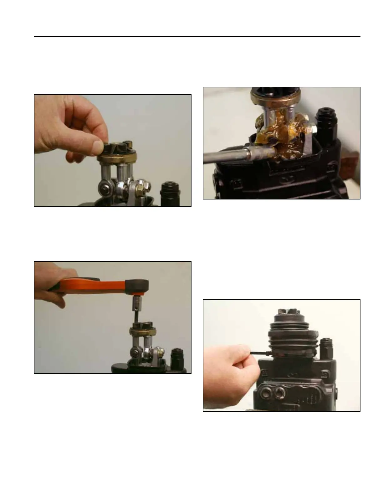
23. Position the articulated holder with 3 hex head
screws and lock washers onto the valve assembly
and thread the 3 bolts onto the joystick joints (Fig.
1171).
25. Lubricate all of the articulated parts inside the
mechanical joystick area with synthetic base grease
grade NLGI2 (Fig. 1173).
Fig 1171 PICT-2602a
Fig 1173 PICT-2655
26. Position the rubber bellows over the base plate
and install the tie strap in the groove of the rubber
bellows (Fig. 1174).
Note: When installing the rubber bellows, there
is an offset in the bellows. Ensure proper
installation.
24. Torque the 3 bolts to 17.7 ft-lbs. (24 Nm) (Fig. 1172).
Fig 1174 PICT-2605a
Fig 1172 PICT-2603a