HYDRAULIC SYSTEM
6-100 Rev. 000 TX525 Service Manual
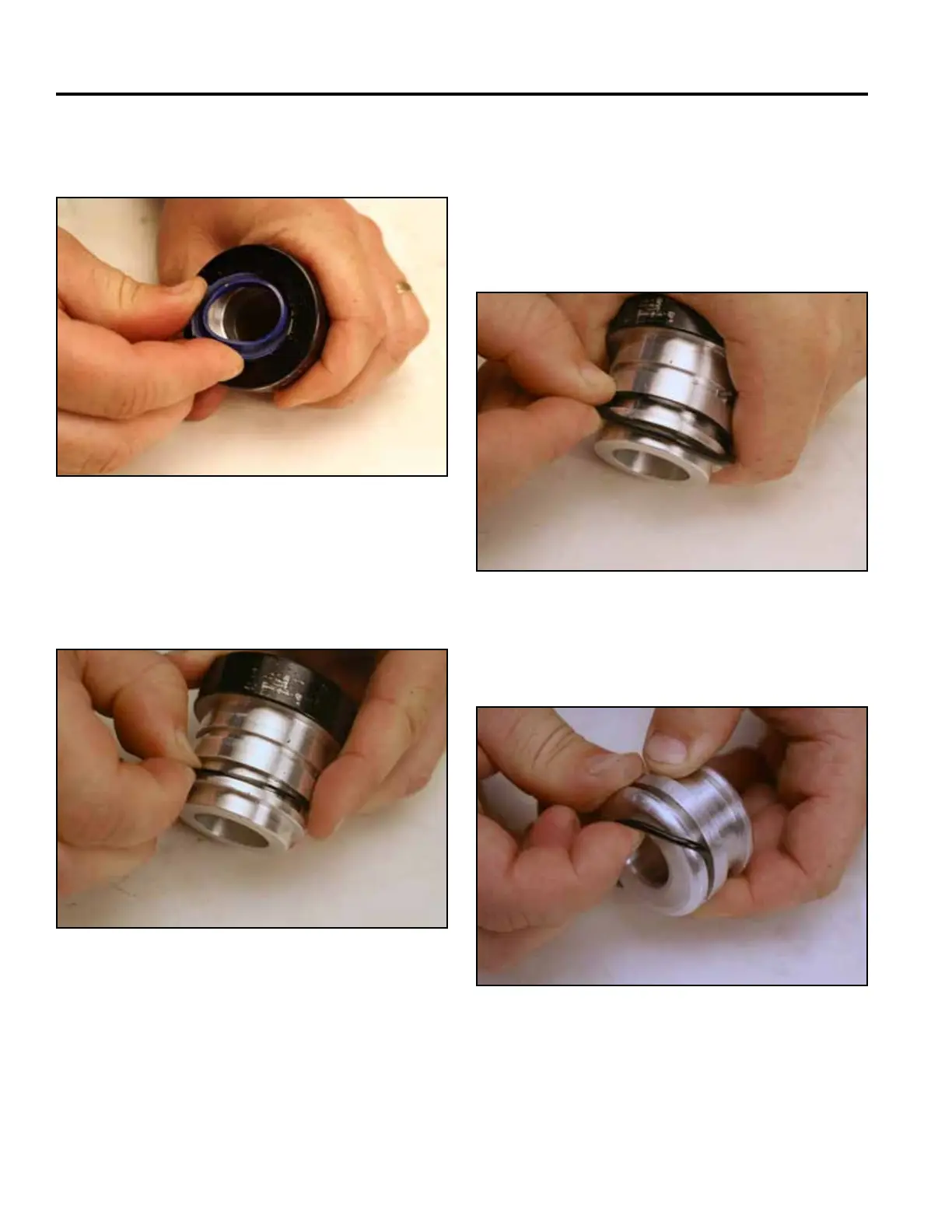
15. Install the wiper seal so that the lip of the seal is
installed in the groove inside the head (Fig. 1211).
17. Install the o-ring into the groove next to the at back-
up ring. The o-ring is installed on the barrel side of
the groove (Fig. 1213).
Note: If possible, the head/seal assembly should
sit for at least one hour to allow the seals to
normalize.
Fig 1211 PICT-3058
Fig 1213 PICT-3060a
18. Install the back-up ring into the piston (Fig. 1214).
16. Install the at back-up ring into the head. The at
back-up seal is installed up against the ram side of
the groove (Fig. 1212).
Fig 1214 PICT-3061a
Fig 1212 PICT-3059a