HYDRAULIC SYSTEM
6-99TX525 Service Manual Rev. 000
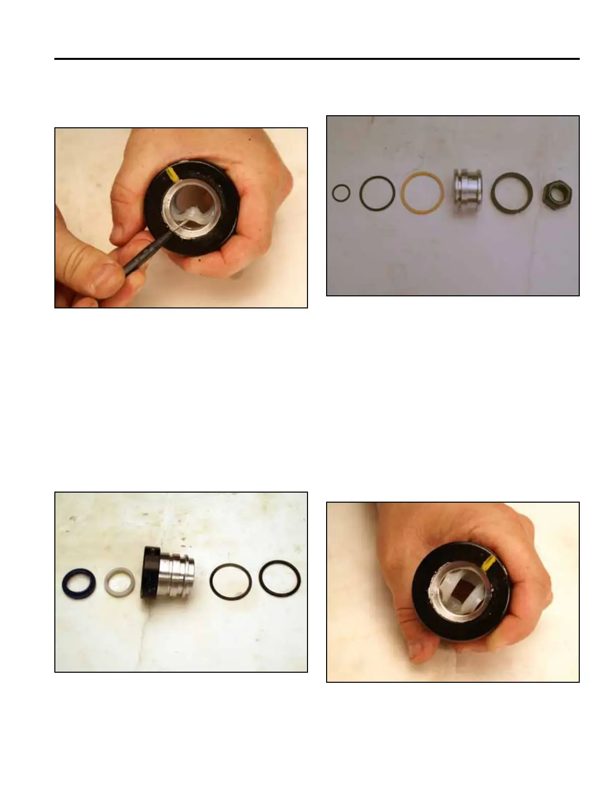
11. Remove the wear seal from inside the head (Fig.
1207).
Piston Assembly (Fig. 1209):
Fig 1207 PICT-3051
Fig 1209 PICT-3056a
14. Lubricate the head and all seals with 10W-30 oil
prior to installation. Twist the wear seal into a “C”
shape and allow it to snap into the groove (Fig.
1210).
Note: The groove of the seal faces toward the barrel
side of the head.
12. Thoroughly rinse the inside of the head with a clean
solvent. Rinse and clean all internal components of
any foreign material with a lint-free rag.
13. Visually inspect for material defects and contami-
nation. All seals and o-rings must be replaced with
new parts.
Head Assembly (Fig. 1208):
Fig 1210 PICT-3057
Fig 1208 PICT-3052
A. Wiper D. Static Back-up
B. Wear Seal E. Static O-Ring
C. Head
A B
C
D
E
A. Piston Inner O-ring D. Piston
B. Backup Piston Seal E. Wear Ring
C. Piston Seal F. Locknut
A
B
C D E
F