DRIVE SYSTEM
7-9TX525 Service Manual Rev. 000
3. Using a spring tool, install the idler spring onto its
post (Fig. 1291).
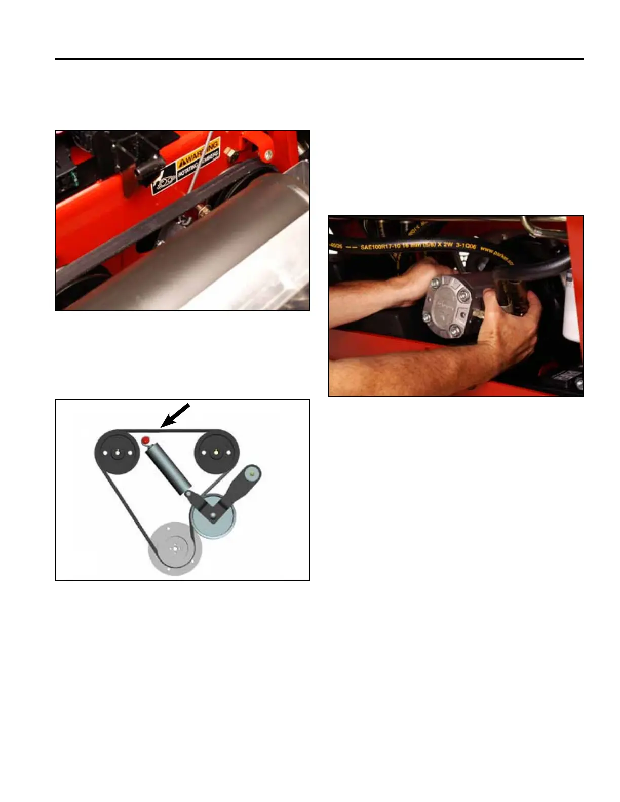
Belt Routing (rear view) (Fig. 1292):
Fig 1291 Belt 007
4. Rotate and push the hydraulic pump by hand until
the coupling sleeve properly meshes with the hub
sleeve recessed in the engine pulley (Fig. 1293).
Note: Do not use the hydraulic pump mount plate
bolts to draw the coupling sleeve into the hub
sleeve. Doing so could result in the snap ring
sliding out of its groove on the hub coupling.
This will result in the loss of hydraulics.
Fig 1293 Belt 012
Fig 1292 TX525 belt routing
A. LH pump pulley D. Idler pulley
B. Drive belt E. Engine pulley
C. RH pump pulley
A C
D
E
B