DRIVE SYSTEM
7-17TX525 Service Manual Rev. 000
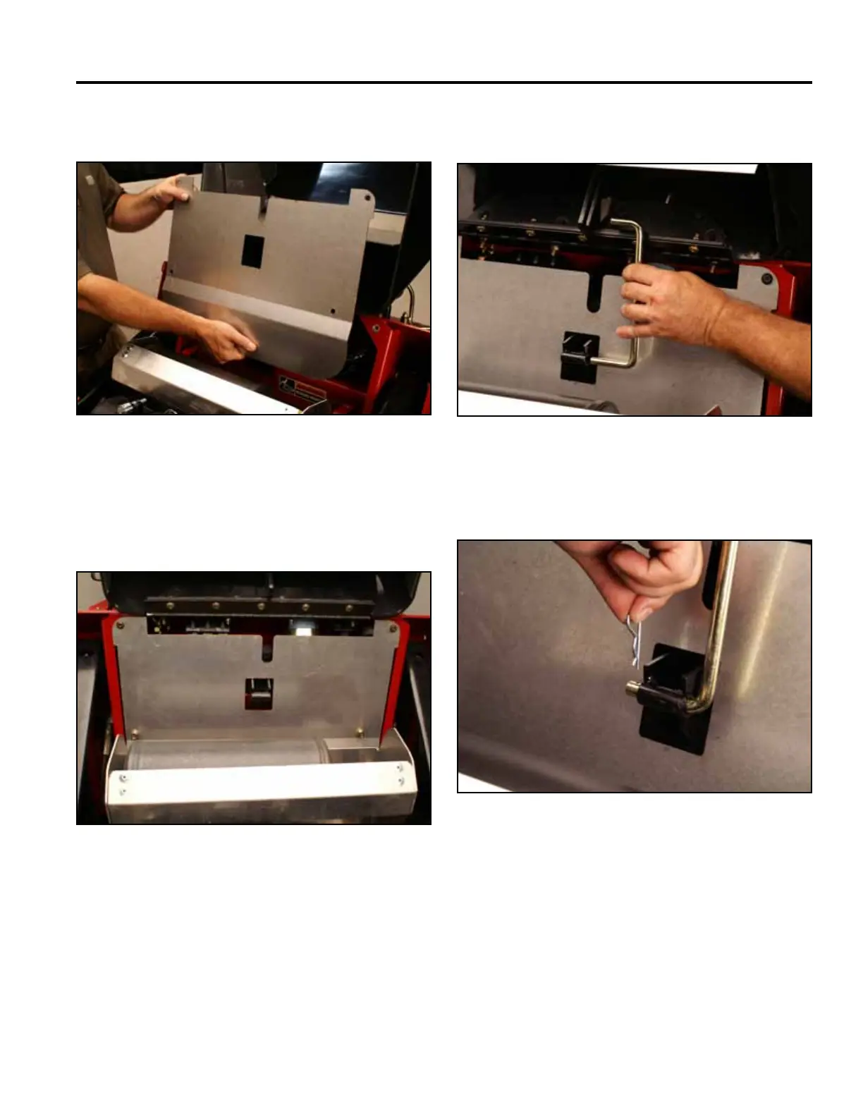
10. Position the heat shield (Fig. 1321). 12. Install the prop rod (Fig. 1323).
Fig 1321 Belt 005
Fig 1323 Belt 003
13. Install a hairpin cotter into the prop rod (Fig. 1324).
11. Using a 3/16” Allen wrench, install the top 2 screws.
Using a 1/2” socket, install the bottom 2 screws
securing the heat shield to the tower (Fig. 1322).
Fig 1324 Belt 001
Fig 1322 PICT-5258