DRIVE SYSTEM
7-19TX525 Service Manual Rev. 000
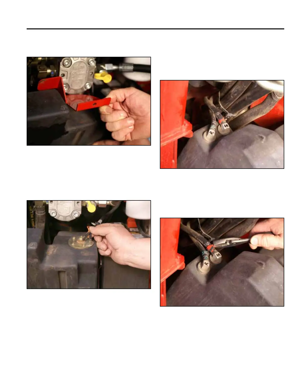
5. Remove the fuel tank bracket (Fig. 1328).
Fig 1328 PICT-5626
6. Disconnect the two wires (black and orange) from
the fuel sending unit located on the top of the fuel
tank (Fig. 1329).
8. Slide the 2 fuel hose clamps down the fuel lines
awayfromthefueltankttings(Fig.1331).
Fig 1329 PICT-4262a
Fig 1331 PICT-4264
7. Markthesuctionfuellineandtankttingwithan“S”
andthereturnfuellineandtankttingwithan“R”
(Fig. 1330):
S - Fuel suction line
R - Fuel return line
Fig 1330 PICT-4263