DRIVE SYSTEM
7-20 Rev. 000 TX525 Service Manual
9. Slidethe2fuellinesoffthefueltankttings.
Remove the fuel tank (Fig. 1332).
Fig 1332 PICT-4265
10. Using a 3/8” socket, remove the 4 self-tapping
screws securing the left hand panel to the control
panel assembly (Fig. 1333).
Fig 1333 PICT-4600
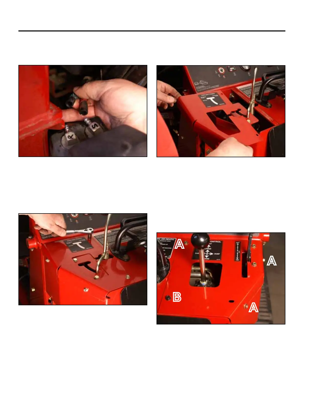
12. Using a 3/8” socket, remove the 3 self-tapping
screws that secure the right panel to the control
panel assembly. Using a 3/8” socket and a 7/16”
socket, remove the bolt and nut securing the lower
left corner of the right panel to the control panel
assembly (Fig. 1335).
Fig 1335 PICT-4341
11. Remove the left hand panel from the control panel
assembly (Fig. 1334).
Fig 1334 PICT-4601
A. Self-tapping screw (3) B. Bolt and nut
A
A
A
B