DRIVE SYSTEM
7-21TX525 Service Manual Rev. 000
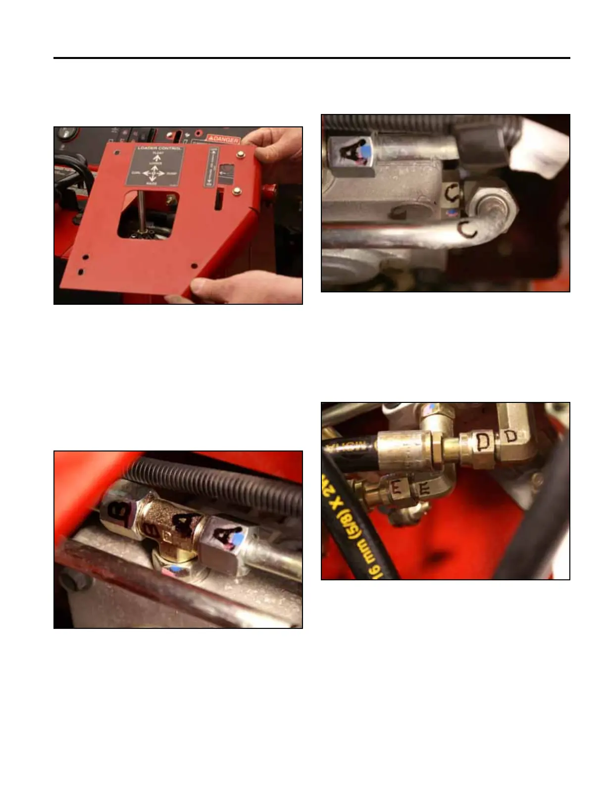
13. Remove the right hand panel from the control panel
assembly (Fig. 1336).
Fig 1336 PICT-4269
14. Markthehydrostaticpumpttingsandlinesas
follows:
A. Inlet line from the left hand hydrostatic pump
(Fig. 0000).
B. Inletlinefromthehydraulicoillter(Fig.1337).
Fig 1337 PICT-4637
C. Case drain line (Fig. 1338).
Fig 1338 PICT-4639a
D. Right hand wheel motor port (Fig. 1339).
E. Left hand wheel motor port (Fig. 1339).
Fig 1339 PICT-4640