DRIVE SYSTEM
7-31TX525 Service Manual Rev. 000
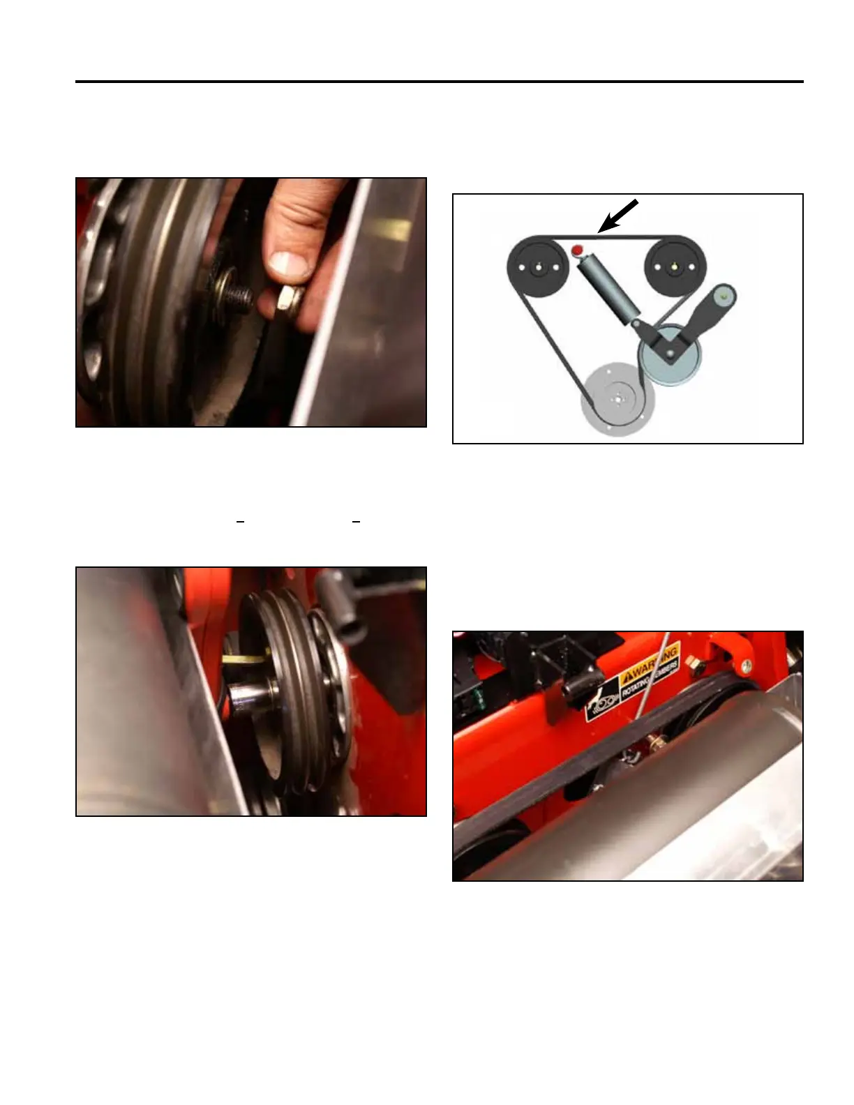
6. Install a nut to secure the pulley to the right hand
hydrostatic pump shaft (Fig. 1376).
Fig 1376 PICT-4761
7. Torque the nut to 260 + 40 in-lbs. (29.38 + 4.5 Nm)
(Fig. 1377).
Fig 1377 PICT-4763
8. Route the belt around the engine pulley and the right
and left hydrostatic pump pulleys (rear view) (Fig.
1378).
Fig 1379 Belt 007
9. Install the idler spring onto its post (Fig. 1379).
A. LH pump pulley D. Idler pulley
B. Drive belt E. Engine pulley
C. RH pump pulley
Fig 1378 TX525 belt routing
A C
D
E
B