DRIVE SYSTEM
7-37TX525 Service Manual Rev. 000
27. Slidethe2fuellinesontothefueltankttings.Note
the location markings (Fig. 1400).
S - Fuel suction line
R - Fuel return line
Note: Before installing the fuel tank in the unit,
dis engage the park brake and start the unit.
Refer to “Purging Air Procedure”, page 9-19,
and check for any leaks in the hydraulic
ttingsandhydraulichoses.
Fig 1400 PICT-4265
28. Position the 2 fuel hose clamps to secure the fuel
linestothefueltankttings(Fig.1401).
30. Position the fuel tank bracket onto the fuel tank (Fig.
1403).
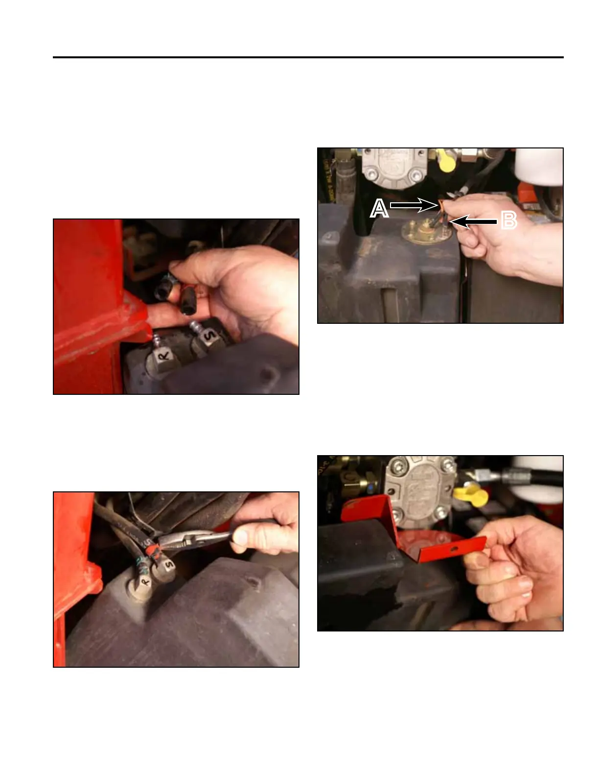
A. Center terminal (orange wire)
B. Outside terminal (black wire)
Fig 1401 PICT-4264
Fig 1403 PICT-5626
29. Position the fuel tank into the rear end of the frame.
Connect the two wires (black and orange) to the fuel
sending unit located on the top of the fuel tank (Fig.
1402).
Fig 1402 PICT-4262a
A
B