DRIVE SYSTEM
7-36 Rev. 000 TX525 Service Manual
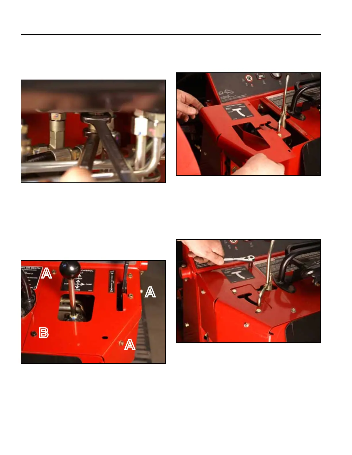
23. Withthettingsecured,tightenthepumpttingnuts
onthettingsmarked“D”and“E”tothehydraulic
pump (Fig. 1396).
Fig 1396 PICT-4756
24. Using a 3/8” socket, install 3 self-tapping screws that
secure the right panel to the control panel assembly.
Using a 3/8” socket and a 7/16” socket, install a bolt
and nut securing the lower left corner of the right
panel to the control panel assembly (Fig. 1397).
Fig 1397 PICT-4341
A. Self-tapping screw (3) B. Bolt and nut
A
A
A
B
25. Position the left hand panel onto the control panel
assembly (Fig. 1398).
Fig 1398 PICT-4601
26. Using a 3/8” socket, install 4 self-tapping screws
securing the left hand panel to the control panel
assembly (Fig. 1399).
Fig 1399 PICT-4600