DRIVE SYSTEM
7-41TX525 Service Manual Rev. 000
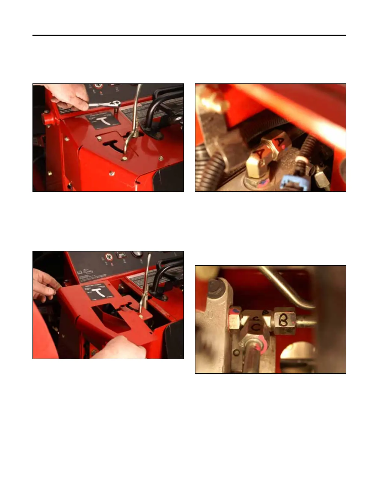
10. Using a 3/8” socket, remove the 4 self-tapping
screws securing the left hand panel to the control
panel assembly (Fig. 1415).
Fig 1415 PICT-4600
11. Remove the left hand panel from the control panel
assembly (Fig. 1416).
Fig 1416 PICT-4601
12. Markthehydrostaticpumpttingsandlinesas
follows:
A. Hydraulicoilinletfromthelter(Fig.1417).
Fig 1417 PICT-4603
B. Right pump case drain line and,
C. Case drain line returning to the hydraulic oil tank
(Fig. 1418).
Fig 1418 PICT-4606