DRIVE SYSTEM
7-42 Rev. 000 TX525 Service Manual
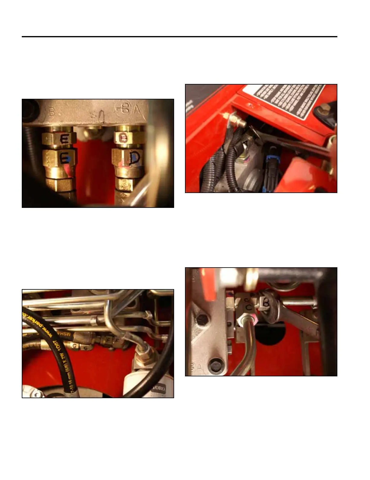
D. Hydraulic hose running to the lower port on the
right hand wheel motor and,
E. Hydraulic hose running to the upper port on the
right hand wheel motor (Fig. 1419).
Fig 1419 PICT-4608
F. Hydraulic hose running to the lower port on the
left hand wheel motor and
G. Hydraulic hose running to the upper port on the
left hand wheel motor (Fig. 1420).
Fig 1420 PICT-4609
13. Using a 15/16” wrench, disconnect the left hand
hydraulic pump lines (just marked) as follows:
A. Hydraulicoilinletfromthelter(Fig.1421).
Fig 1421 PICT-4612
B. Right pump case drain line (Fig. 1422).
Note: A7/8”wrenchmaybeusedtoholdthetting
while loosening the hydraulic line.
Fig 1422 PICT-4613