DRIVE SYSTEM
7-55TX525 Service Manual Rev. 000
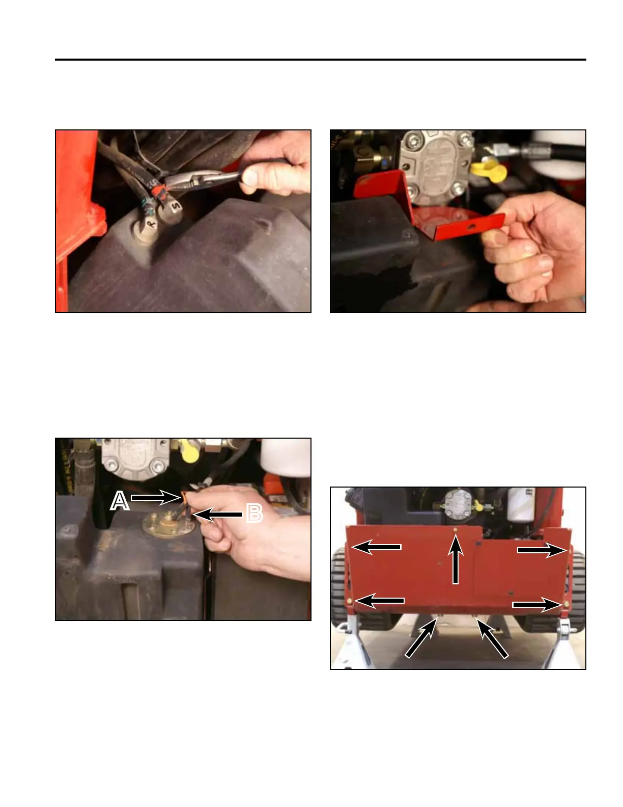
24. Position the fuel tank into the rear end of the frame.
Connect the two wires (black and orange) to the fuel
sending unit located on the top of the fuel tank (Fig.
1471).
Fig 1471 PICT-4262
25. Position the fuel tank bracket onto the fuel tank (Fig.
1472).
A. Center terminal (orange wire)
B. Outside terminal (black wire)
23. Position the 2 fuel hose clamps to secure the fuel
linestothefueltankttings(Fig.1470).
Fig 1472 PICT-5626
Fig 1470 PICT-4264
26. Position the rear frame cover to the rear end of the
frame. Using 3/4” and 1/2” sockets, install 7 bolts
and nuts to secure the rear frame cover to the frame
and fuel tank bracket (Fig. 1473).
Note: The rear of the machine may have to be lifted
to reposition the jack stands so that the rear
frame cover can be installed.
Fig 1473 PICT-4259
A
B