DRIVE SYSTEM
7-54 Rev. 000 TX525 Service Manual
20. Position the left hand panel onto the control panel
assembly (Fig. 1467).
Fig 1467 PICT-4601
21. Using a 3/8” socket, install 4 self-tapping screws
securing the left hand panel to the control panel
assembly (Fig. 1468).
Fig 1468 PICT-4600
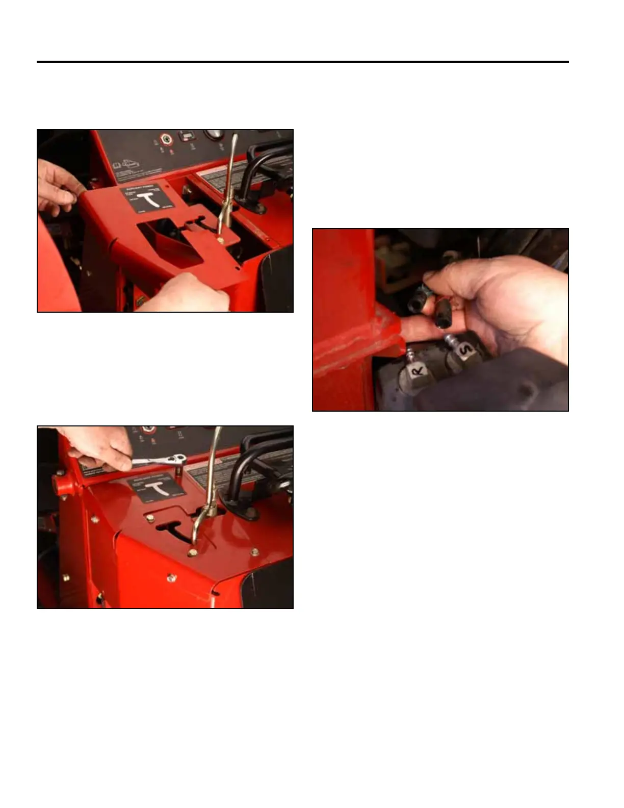
22. Slidethe2fuellinesontothefueltankttings.Note
the location markings (Fig. 1469).
S - Fuel suction line
R - Fuel return line
Note: Before installing the fuel tank into the unit,
disengage the park brake and start the unit.
Refer to “Purging Air Procedure”, page 9-19,
and check for any leaks in the hydraulic
ttingsandhydraulichoses.
Fig 1469 PICT-4265