DRIVE SYSTEM
7-53TX525 Service Manual Rev. 000
B. Right pump case drain line (Fig. 1463).
Note: A 7/8” wrench may need to be used to hold
thettingwhiletighteningthehydraulicline.
Fig 1463 PICT-4613
A. Hydraulicoilinletfromthelter(Fig.1464).
Fig 1464 PICT-4612
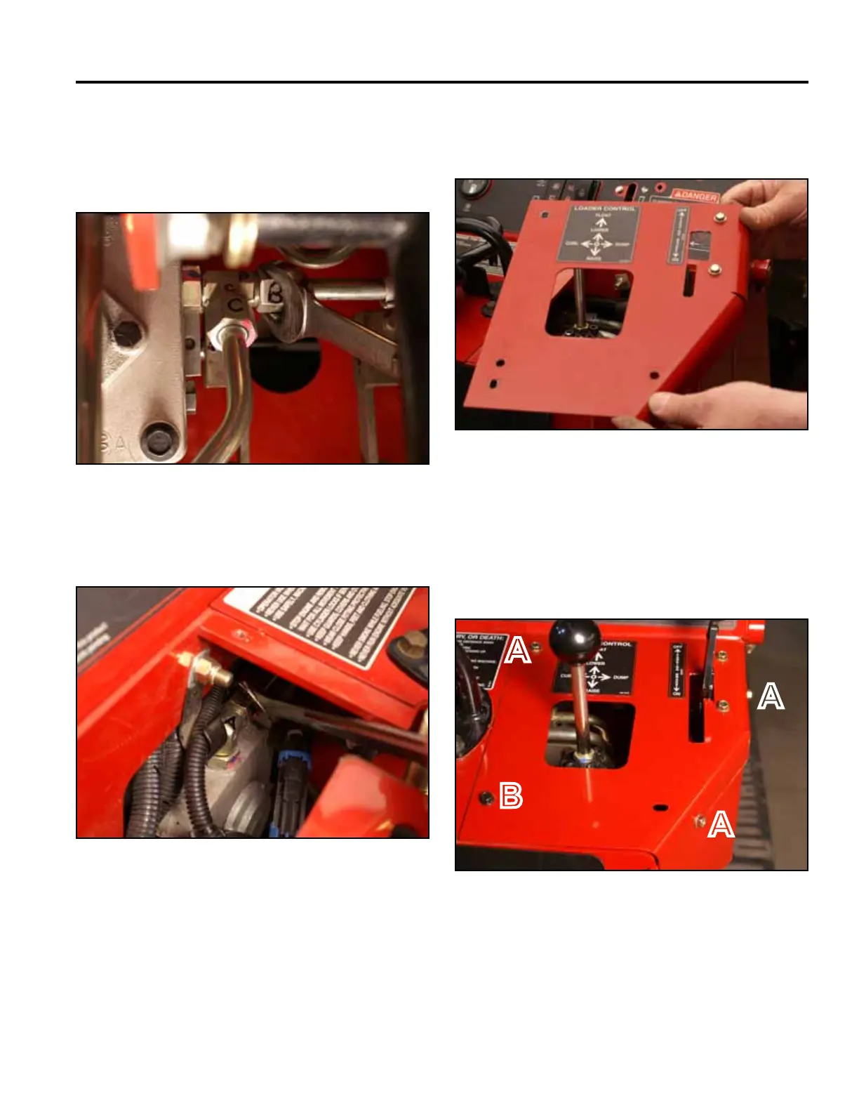
18. Position the right hand panel onto the control panel
assembly (Fig. 1465).
A. Self-tapping screw (3) B. Bolt and nut
Fig 1465 PICT-4269
19. Using a 3/8” socket, install 3 self-tapping screws that
secure the right panel to the control panel assembly.
Using a 3/8” socket and a 7/16” socket, install a bolt
and nut securing the lower left corner of the right
panel to the control panel assembly (Fig. 1466).
Fig 1466 PICT-4341
A
A
A
B