DRIVE SYSTEM
7-85TX525 Service Manual Rev. 000
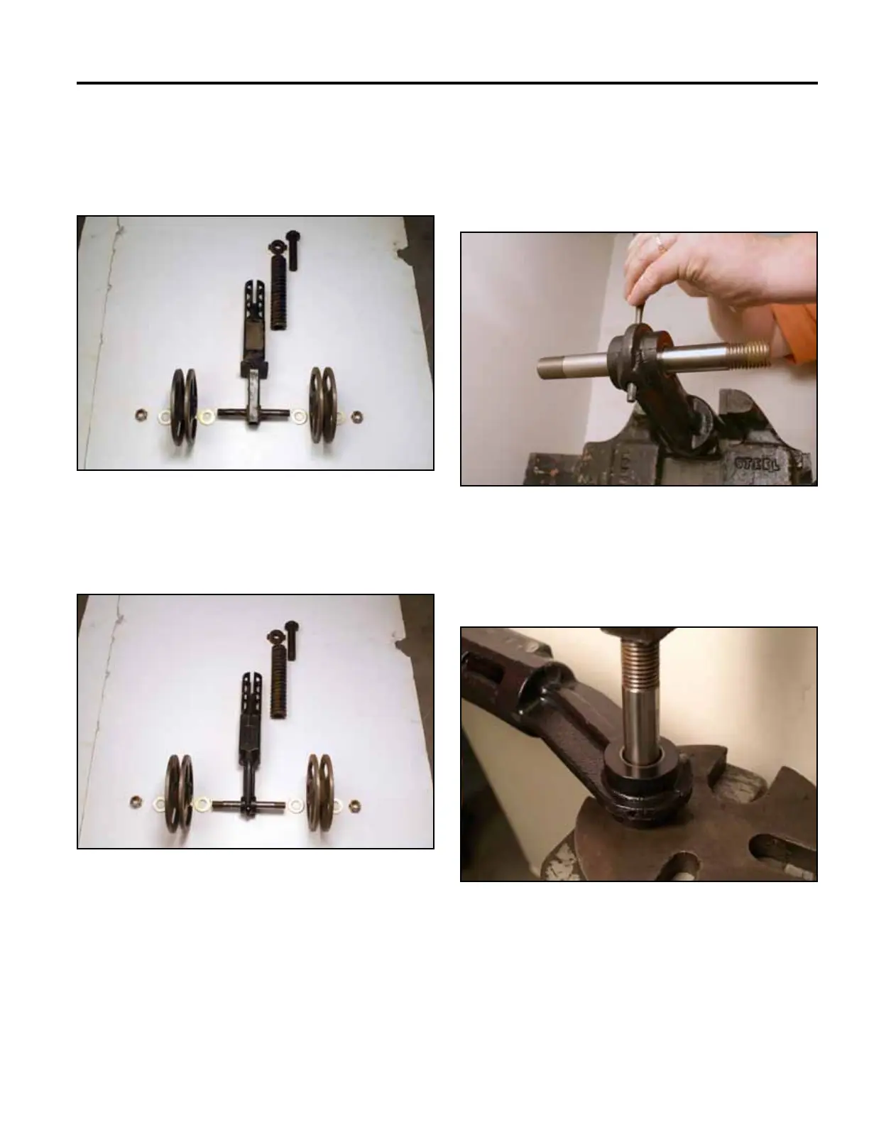
Tensioner Arm and Wheel Assembly (Fig. 1578 and Fig.
1579)
Welded, non-replaceable style (serial #270000001 -
270999999):
Fig 1578 PICT-4566a
Cast, replaceable style (serial #280000001 & up):
Fig 1579 PICT-4567a
7. Secure the tensioner arm into a vise with the bottom
side facing up.
8. Drive the roll pin out of the shaft end of the tensioner
arm (Fig. 1580).
Fig 1580 PICT-4549a
9. Press the tensioner arm shaft out of the tensioner
arm (Fig. 1581).
Fig 1581 PICT-4550