DRIVE SYSTEM
7-92 Rev. 000 TX525 Service Manual
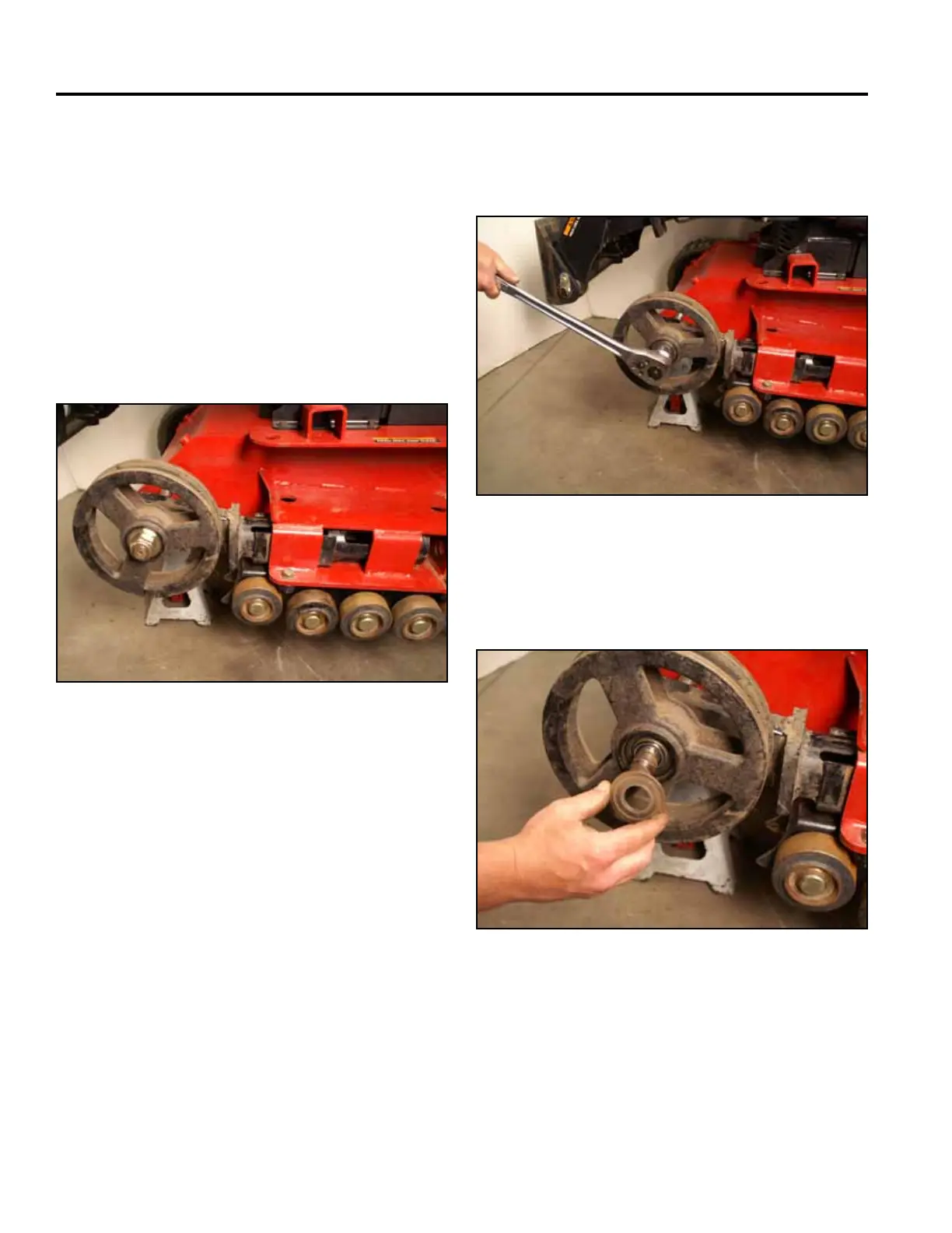
14. Using a 1-1/2” socket, remove the nut securing the
inner tensioner wheel to the tensioner arm shaft
(Fig. 1604).
10. Clean the tensioner arm wheel of all grease and
debris. Replaced if damaged or worn.
Inner tensioner wheel bearing removal:
11. Raise the loader arm approximately 12” (30.48cm).
12. Remove the track. Refer to “Wide Track Removal”
on page 7-68.
13. Rotate the tensioner arm so the bottom of the ten-
sioner arm is facing up and slide it back into the
mainframe so that the square portion of the tension-
er arm is inserted into the mainframe (Fig. 1603).
Fig 1604 PICT-4572
Fig 1603 PICT-4571
15. Remove the outer washer from the tensioner wheel
(Fig. 1605).
Fig 1605 PICT-4574