BRAKES
8-12 Rev. 000 TX525 Service Manual
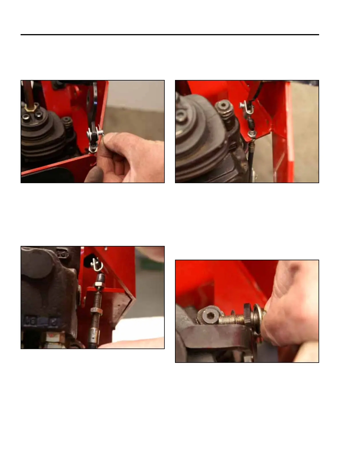
4. Secure the brake cable to the brake handle with a
clevis pin. Install the cotter pin into the clevis pin
(Fig. 1677).
Fig 1677 PICT-4304
5. Pull down on the cable and slide the threaded
portion of the brake cable assembly into the slot in
the control panel (Fig. 1678).
Fig 1678 PICT-4305
6. Thread the upper nut onto the threaded portion of
the brake cable down to the control panel slot (Fig.
1679).
Fig 1679 PICT-4306
7. Install the shoulder bolt and 2 spring washers
through the handle. (Fig. 1680).
Note: A spring washer is installed on each side of
the brake handle.
Fig 1680 PICT-4307