BRAKES
8-13TX525 Service Manual Rev. 000
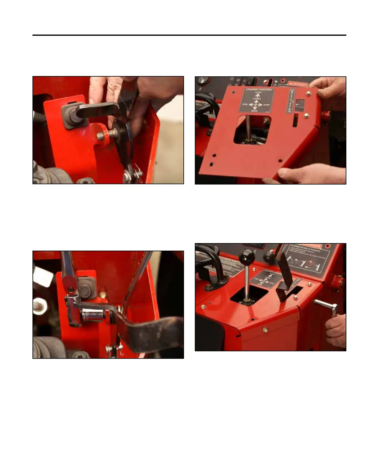
8. Insert the shoulder bolt through the brake support
bracket (Fig. 1681).
Fig 1681 PICT-4308
9. Using a 9/16” socket and wrench, install the nut onto
the shoulder bolt securing the brake handle to the
brake support bracket (Fig. 1682).
Fig 1682 PICT-4309
10. Position the right panel onto the control panel
assembly (Fig. 1683).
Fig 1683 PICT-4269
11. Using a 3/8” socket, install 4 bolts securing the top
right panel to the control panel assembly (Fig. 1684).
Fig 1684 PICT-4268