BRAKES
8-23TX525 Service Manual Rev. 000
24. Push the 2 brake plates outward toward the drive
wheels (Fig. 1721).
Note: The drive wheels may have to rotate to permit
the brake plates to extend fully outward.
Fig 1721 PICT-4367
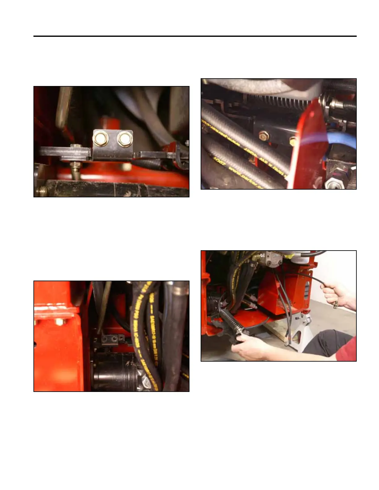
25. Using a 1/2” socket, remove the 2 bolts securing the
brake bar support to the frame (Fig. 1722).
23. Using a 1/2” socket, remove the 2 bolts holding the
left brake plate to the left brake mounting bracket
(Fig. 1720).
Fig 1722 PICT-4371
Fig 1720 PICT-4365a
26. Remove the brake cable assembly from the machine
(Fig. 1723).
Fig 1723 PICT-4373a