BRAKES
8-45TX525 Service Manual Rev. 000
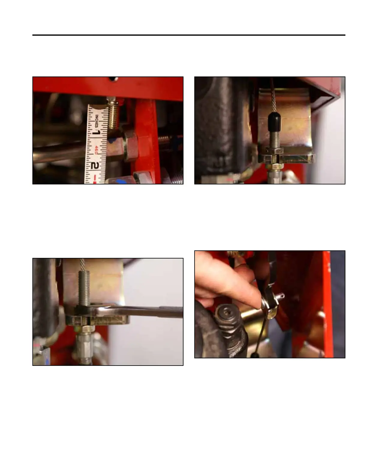
Note: There should be approximately 3/4” (1.9cm) of
exposed thread past the nut (Fig. 1801).
7. Slide the rubber boot onto the threaded portion of
the brake cable (Fig. 1803).
Fig 1801 PICT-4413
Fig 1803 PICT-4420
8. Support the brake handle, align the brake cable
retainer with the brake handle and install a clevis pin
(Fig. 1804).
6. Slide the threaded portion of the brake cable into the
slot of the spring bracket so that the bottom nut is on
the underside of the bracket. Thread the top nut onto
the brake cable and tighten (Fig. 1802).
Fig 1804 PICT-4421
Fig 1802 PICT-4419a