BRAKES
8-46 Rev. 000 TX525 Service Manual
9. Install a cotter pin into the clevis pin attaching the
brake cable to the brake handle (Fig. 1805).
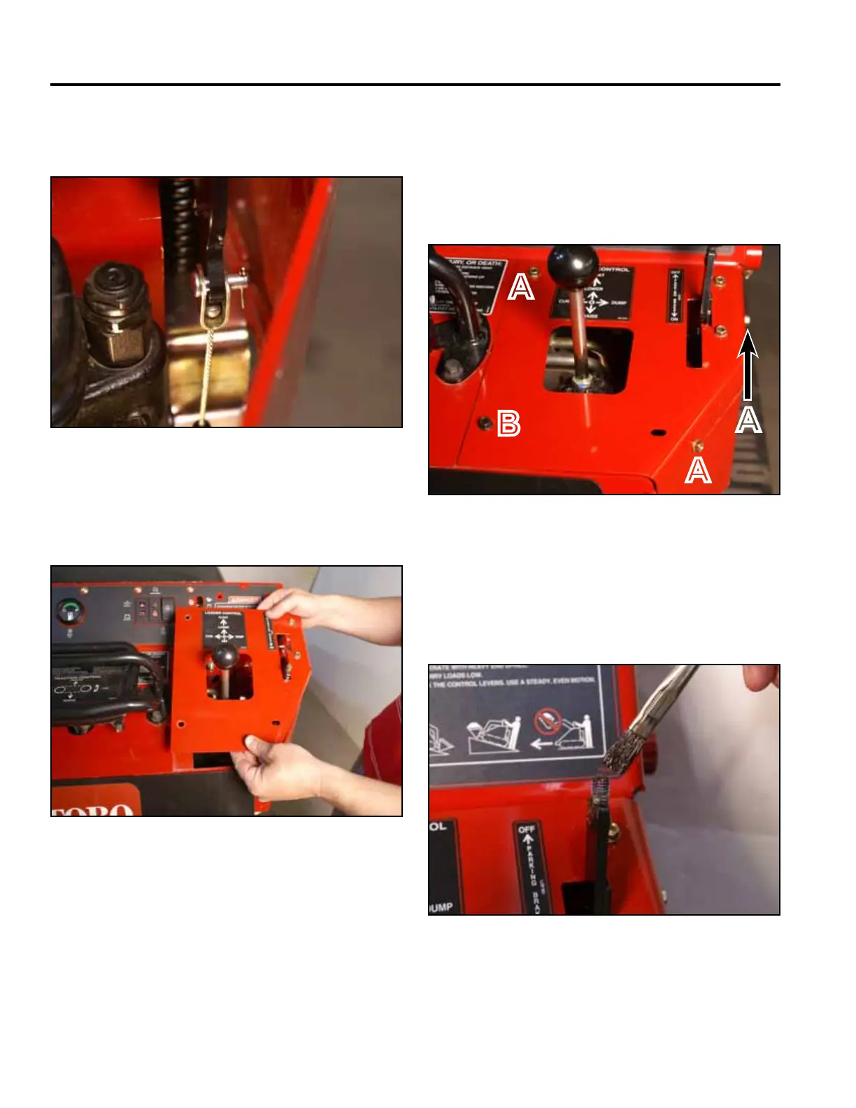
11. Using a 3/8” socket, install 3 self-tapping screws
that secure the top right panel to the control panel
assembly. Using a 3/8” socket and a 7/16” socket,
Install the bolt and nut securing the lower left corner
of the top right panel to the control panel assembly
(Fig. 1807).
Fig 1805 PICT-4422
Fig 1807 PICT-4341
12. Apply thread locking compound (Loctite 416 or
equivalent) to brake handle threads (Fig. 1808).
A. Self-tapping screw (3) B. Bolt and nut
10. Position the top right panel onto the control panel
assembly (Fig. 1806).
Fig 1808 PICT-5526
Fig 1806 PICT-4343a
A
B
A
A