BRAKES
8-47TX525 Service Manual Rev. 000
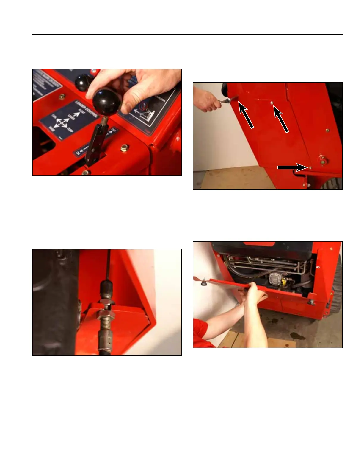
13. Install the knob onto the brake handle (Fig. 1809).
15. Install the rear access panel (Fig. 1812).
Fig 1809 PICT-4342
Fig 1812 PICT-4505a
14. Position the right hand side support bracket. Using
a 3/8” socket, install 3 self-tapping screws to secure
(Fig. 1811).
Fig 1811 PICT-4504
Note: If the brake plates extend out past the frame,
the brake cable adjustment nuts should be
adjusted upward on the brake cable adjust-
ment threads (Fig. 1810).
Fig 1810 PICT-4340