BRAKES
8-52 Rev. 000 TX525 Service Manual
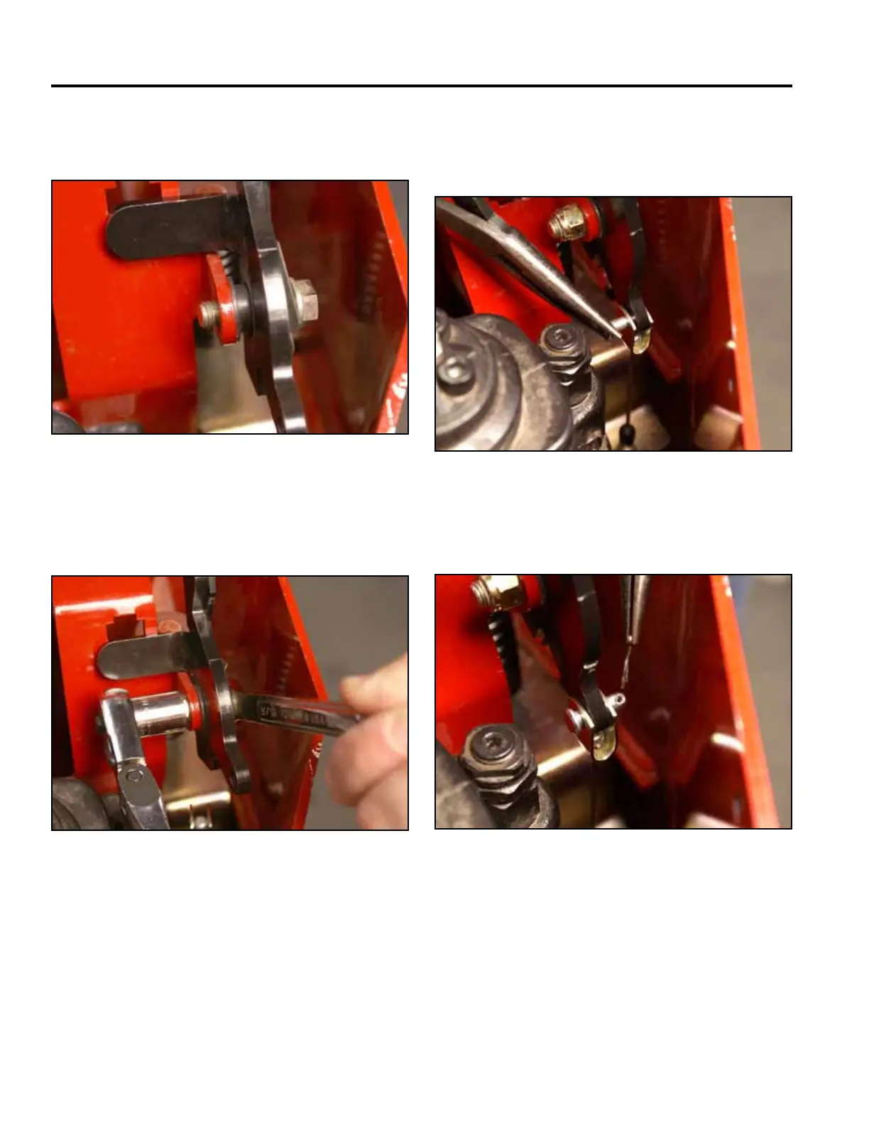
4. Install the brake handle assembly into the control
panel bracket (Fig. 1828).
6. Support the brake handle and install a clevis pin
securing the brake cable to the brake handle (Fig.
1830).
Fig 1828 PICT-4428a
Fig 1830 PICT-4425
7. Install a cotter pin onto the clevis pin (Fig. 1831).
5. Using a 9/16” socket and wrench, install a nut onto
the shoulder bolt (Fig. 1829).
Fig 1831 PICT-4424
Fig 1829 PICT-4426a