BRAKES
8-53TX525 Service Manual Rev. 000
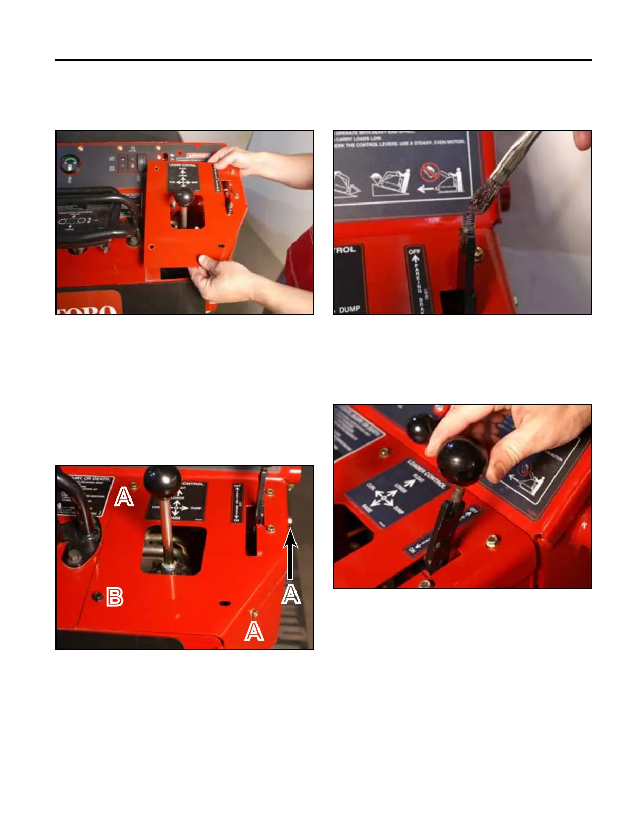
8. Position the right panel onto the control panel
assembly (Fig. 1832).
10. Apply thread locking compound (Loctite 416 or
equivalent) to brake handle threads (Fig. 1834).
A. Self-tapping screw (3) B. Bolt and nut
Fig 1832 PICT-4343a
Fig 1834 PICT-5526
11. Install the knob onto the brake handle (Fig. 1835).9. Using a 3/8” socket, install 3 self-tapping screws
securing the top right panel to the control panel
assembly. Using a 3/8” socket and a 7/16” socket,
install the bolt and nut securing the lower left corner
of the top right panel to the control panel assembly
(Fig. 1833).
Fig 1835 PICT-4342
Fig 1833 PICT-4341
A
B
A
A