9-74
P00D1, P2195
3. Connection of ECU coupler.
• Check the locking condition of the coupler.
• Disconnect the coupler and check the pins (bent or broken terminals and locking condition of the
pins).
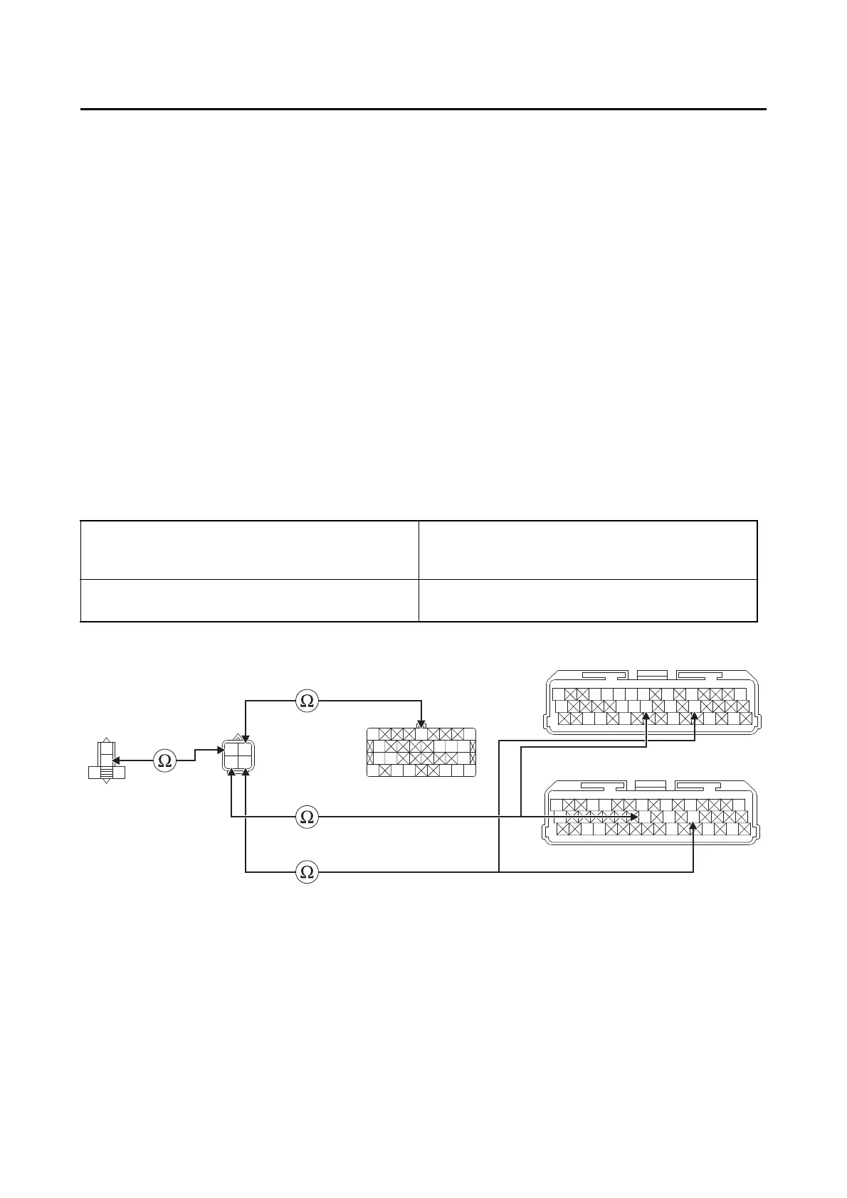
4. Wire harness continuity.
• Disconnect the O
2
sensor coupler, ECU coupler and fuel injection system relay coupler.
• Open circuit check
Is the coupler condition normal?
YES
Go to step 4.
NO
a. Connect the coupler securely or replace the wire harness.
b. Start the engine and let it idle for approximately 1 minute.
c. Check the condition of the DTC using the malfunction mode of the YDT.
Is it in the “Recovered” condition?
YES
Go to step 8, and complete the service.
NO
Go to step 4.
Between O
2
sensor coupler “1” and ECU cou-
pler “2”
black/green–black/green
gray/green–gray/green
black/blue–black/blue
Between O
2
sensor coupler “1” and fuel injec-
tion system relay coupler “3”
red/blue–red/blue
O
B/GY/R
B
R/BG/B
Y/W
B
Y/RR/L
BB
R/LL/Y
Y/W
R
B/Y
L
Y/G
P
Lg/L
O/WW/G
Y/L
Lg/W
B/L
Br/W
Gy/G
G/L
R/G
Lg/L
W/G
W/Y
G/R
Lg/B
L/W
Lg
B/Y
L
Y/G
P
W/G
Y/L
Lg/W
B/L
Br/W
Gy/G
Lg/L
W/G
W/Y
G/RL/W
Lg
R
R/L
R/B
L/Y
R/L
B/G
Gy/G
B/L
1
2
3
2
*
2
**
*. XP560D
**. XP560E
Is resistance 0 ?
YES
Go to “Short circuit check”.
NO
a. Replace the wire harness.
b. Start the engine and let it idle for approximately 1 minute.
c. Check the condition of the DTC using the malfunction mode of the YDT.
 Loading...