n
Speed Limitation and Speed Limit Bias
The speed limit setting is read from the input selected in parameter d5-03. A bias can be added to this speed limit using
parameter d5-05 while parameter b5-08 determines how the speed limit bias is applied. Table 5.20 explains the relation between
these settings.
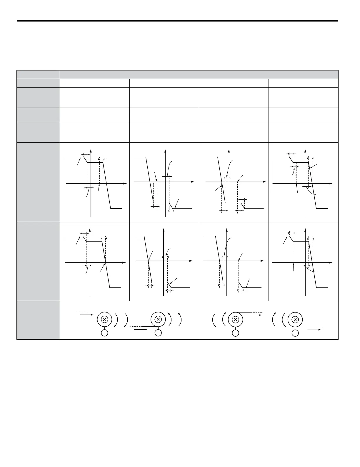
Table 5.20 Speed Limit, Speed Bias and Speed Limit Priority Selection
Operating Conditions
Run Command Forward Forward Forward Forward
Torque
Reference
Direction
Positive (Forward) Negative (Reverse) Negative (Reverse) Positive (Forward)
Speed Limit
Direction
Positive (Forward) Negative (Reverse) Positive (Forward) Negative (Reverse)
Normal
Operation
Direction
Forward Reverse Forward Reverse
Generated
Torque
(d5-08 = 0)
<1>
Speed
Torque
Torque
Limit
Internal
Torque
Reference
0
Torque
Limit
Speed
Limit
Δn
Speed Limit
Bias d5-05
Speed Limit
Bias d5-05
Speed
Torque
Torque
Limit
Internal
Torque
Reference
0
Torque
Limit
Speed
Limit
Δn
Speed Limit
Bias d5-05
Speed Limit
Bias d5-05
Dn
Speed
Torque
d5-05
Torque
Limit
Internal
Torque
Reference
0
Torque
Limit
Speed Limit
Δn
Speed Limit
Bias d5-05
Speed
Torque
Torque
Limit
Internal
Torque
Reference
0
Torque
Limit
Speed
Limit
Speed
Limit Bias
d5-05
Δn
Δn
Speed
Limit Bias
d5-05
Generated
Torque
(d5-08 = 1)
<1>
Speed
Torque
Δn
Torque
Limit
Internal
Torque
Reference
0
Torque
Limit
Speed
Limit Bias
d5-05
Speed
Limit
Δn
Speed
Torque
Torque
Limit
Internal
Torque
Reference
0
Torque
Limit
Speed Limit
Bias d5-05
Speed
Limit
Δn
Δn
Δn
Speed
Torque
Torque
Limit
Internal
Torque
Reference
0
Torque
Limit
Speed Limit
Bias d5-05
Speed Limit
Δn
Speed
Torque
Torque
Limit
Internal
Torque
Reference
0
Torque
Limit
Speed
Limit
Speed
Limit Bias
d5-05
Δn
Δn
Application
Example
Winder
Speed
Line Direction
M
Torque
M
Line Direction
Speed Torque
Unwinder
Torque
Line Direction
M
Speed
M
Line Direction
Torque Speed
<1>
The value of delta n in the drawings depends on the ASR setting in parameters C5-oo.
n
Indicating Operation at the Speed Limit
Program a digital output to close when the drive operates at or beyond the speed limit (H2-oo = 32). Use this output to notify
a control device such as a PLC of abnormal operating conditions.
n
Switching Between Torque and Speed Control
Use a digital output to switch Torque Control and Speed Control (H1-oo = 71). When switching from Speed Control to
Torque Control, the torque limit becomes the torque reference and the speed reference becomes the speed limit. This change
is reversed when switching back to Speed Control.
5.4 d: Reference Settings
180
YASKAWA ELECTRIC SIEP C710616 31B YASKAWA AC Drive – A1000 Technical Manual

 Loading...


