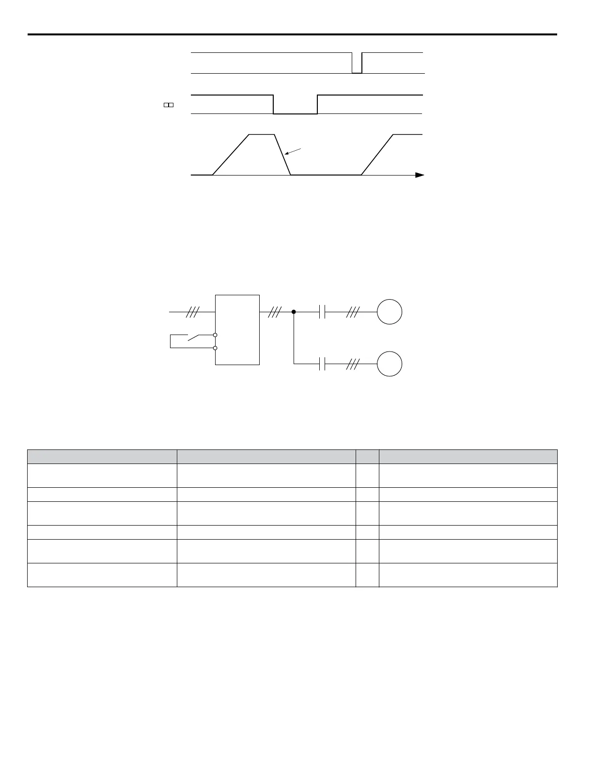
Run/Stop
TIME
Fast-Stop
H1- = 17
Decelerates at C1-09
ON ON
ONON
Output Frequency
Figure 5.60 Fast Stop Sequence
NOTICE: Rapid deceleration can trigger an overvoltage fault. When faulted, the drive output shuts off, and the motor coasts. To avoid this
uncontrolled motor state and to ensure that the motor stops quickly and safely, set an appropriate Fast Stop time to C1-09.
Setting 16: Motor 2 Selection
The drive has the capability to control two induction motors independently. A second motor may be selected using a multi-
function digital input as shown in Figure 5.61.
Note: The motor 2 selection function cannot be used with PM motors.
M
M
Drive
Motor 1
Motor 2
Motor switch input
Figure 5.61 Motor Selection
When switching between motor 1 and motor 2, the parameters used to control those motors also change. Below, Table 5.32
lists the parameters that correspond to each motor:
Table 5.32 Parameters for Switching Between Two Motors
No. Setting 16 Open (Motor 1)
⇒
Setting 16 Closed (Motor 2)
C1-oo: Acceleration/Deceleration
Time
C1-01 to C1-04
⇒
C1-05 to C1-08
C3-oo : Motor Slip Compensation
C3-01 to C3-04, C3-15
⇒
C3-21 to C3-25
C4-oo: Motor Torque
Compensation
C4-01
⇒
C4-07
C5-oo: Speed Control (ASR)
C5-01 to C5-08, C5-12, C5-15, C5-17, C5-18
⇒
C5-21 to C5-28, C5-32, C5-35, C5-37, C5-38
E1-oo, E3-oo: V/f Pattern
E2-oo, E4-oo: Motor Parameters
E1-oo, E2-oo
⇒
E3-oo to E4-oo
F1-oo (PG Constant)
F1-01 to F1-21
⇒
F1-02 to F1-04, F1-08 to F1-11, F1-14, F1-31
to F1-37
Note: 1. When using 2 motors, the motor overload protection selection (oL1) set to L1-01 applies to both motor 1 and motor 2.
2. Attempting to switch between motor 1 and motor 2 during run will trigger the rUn alarm.
3. There is a 500 ms delay when switching between motors equipped with a PG encoder for feedback.
4. The motor 2 selection function cannot be used with PM motors.
If a digital output is programmed for “Motor 2 selection” (H1-01, H1-02, or H1-03 = 1C), the motor will be selected when
the output is closed.
Setting 18: Timer Function Input
This setting configures a digital input terminal as the input for the timer function. Use this setting combination with the timer
function output (H2-oo = 12). Refer to b4: Delay Timers on page 140 for details.
5.7 H: Terminal Functions
212
YASKAWA ELECTRIC SIEP C710616 31B YASKAWA AC Drive – A1000 Technical Manual

 Loading...


