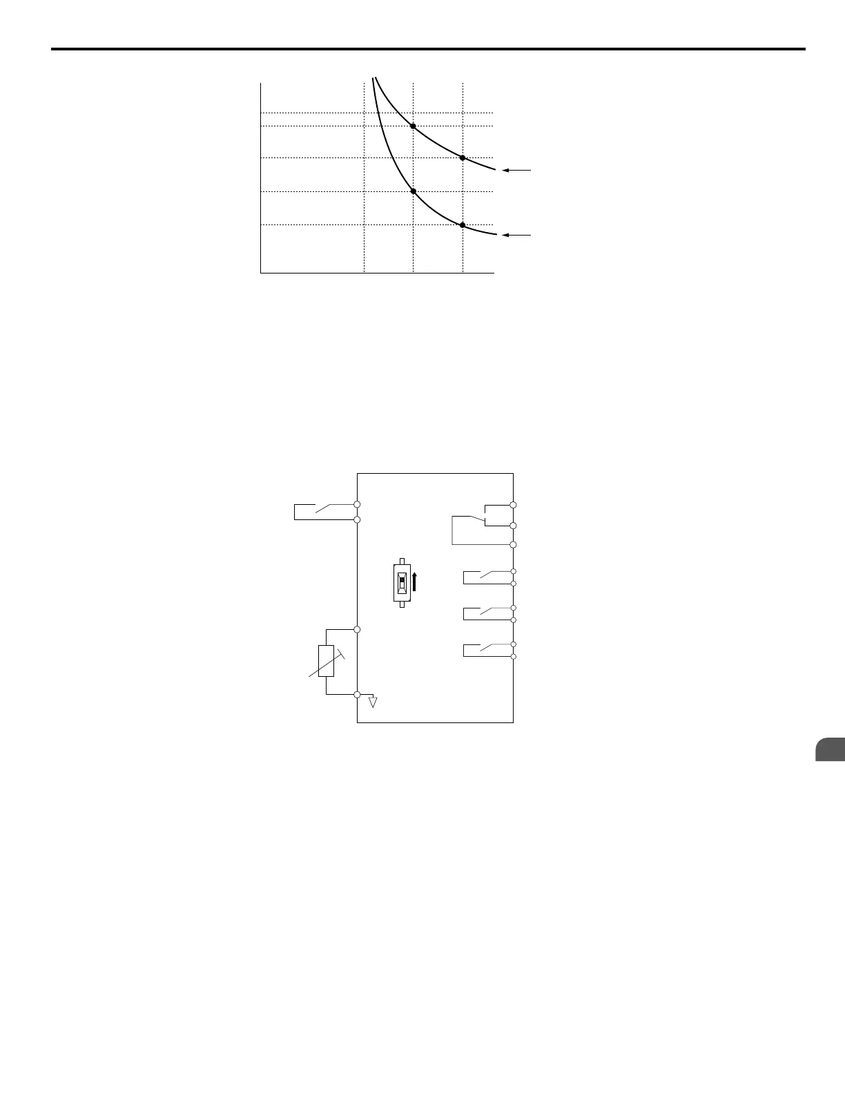
Operation time (minutes)
Cold start
Hot start
Motor current (%)
E2-01 = 100% motor current
10
7
3
1
0.4
0.1
0 100 150 200
Figure 5.87 Motor Protection Operation Time
n
Motor Protection Using a Positive Temperature Coefficient (PTC)
Connect a motor PTC can to an analog input of the drive for motor overheat protection.
The motor overheat alarm level triggers an oH3 alarm and the drive continues the operation selected in L1-03. The overheat
fault level triggers an oH4 fault, outputs a fault signal, and the drive stops the motor using the stop method selected in L1-04.
Connect the PTC between terminals AC and A3 and set jumper S4 on the terminal board to “PTC” as shown in Figure 5.88.
Set H3-05 to 0 and H3-06 to E.
Drive
Multi-function input
PTC
thermistor
MA
Fault output
Multi-function
digital outputs
MB
MC
A3 (0-10 V)
AC
M1
M2
PTC
AI
DIP Switch S4
M3
M4
M5
M6
Figure 5.88 Connection of a Motor PTC
The PTC must exhibit the characteristics shown in Figure 5.89 in one motor phase. The motor overload protection of the drive
expects 3 of these PTCs to be connected in a series.
5.8 L: Protection Functions
YASKAWA ELECTRIC SIEP C710616 31B YASKAWA AC Drive – A1000 Technical Manual
241
5
Parameter Details

 Loading...


