Choose between System KEB Ride-Thru 1 and 2, (L2-29 = 2 or 3) for applications where multiple drives have to perform
KEB operation while keeping a certain speed ratio.
Single Drive KEB Ride-Thru 1 (L2-29 = 0)
After KEB Ride-Thru begins, the drive uses regenerative energy from the motor to keep the DC bus voltage at the level set
to L2-11 while adjusting the rate of deceleration based on the time set to L2-06.
Note: Shorten the KEB deceleration time (L2-06) if undervoltage (Uv1) occurs in the DC bus. Increase the KEB deceleration time if overvoltage
(ov) occurs.
Single Drive KEB Ride-Thru 2 (L2-29 = 1)
The drive uses information about the inertia of the connected machinery to determine the deceleration rate necessary to keep
the DC bus voltage at the level set in parameter L2-11. The resulting deceleration time is calculated based on the system inertia
and cannot be adjusted.
System KEB Ride-Thru 1 (L2-29 = 2)
The drive decelerates at the KEB deceleration time set to L2-06. L2-06 is the time required decelerate from the current
frequency reference to 0. Using this setting, multiple drives can decelerate while keeping the speed ratio constant between
those drives. This function requires a braking resistor and disregards the voltage level in the DC bus.
System KEB Ride-Thru 2 (L2-29 = 3)
The drive decelerates based on the KEB deceleration time set to L2-06 while monitoring the DC bus voltage. If the voltage
level rises, the drive briefly holds the frequency before continuing to decelerate.
n
KEB Ride-Thru Start
KEB operation is triggered independently of the selected KEB operation mode. When the KEB function is selected as the
function to be executed when power loss operation occurs (L2-01 = 3, 4, or 5), then KEB Ride-Thru will be activated if one
of the following conditions becomes true:
•
A digital input programmed for H1-oo = 65 or 66 is activated. This will start KEB operation using the mode selected in
parameter L2-29.
•
A digital input programmed for H1-oo = 7A or 7B is activated. This will automatically select Single KEB Ride-Thru 2,
disregarding the setting of L2-29.
• The DC bus voltage fell below the level specified in L2-05. The KEB operation will start as specified in L2-29.
Note: Attempting to simultaneously assign KEB Ride-Thru 1 and 2 to input terminals will trigger an oPE3 error.
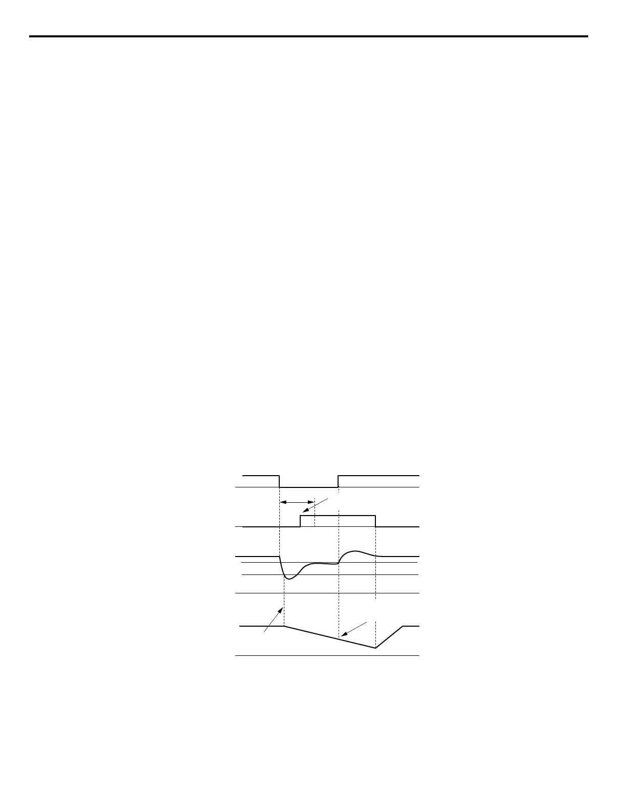
When using a digital input to trigger KEB operation and the device controlling the input acts relatively slow, set a minimum
KEB operation time in parameter L2-10. In the example below, the DC bus voltage triggers KEB operation and a digital input
triggers the Hold command.
L2-05 (Uv Detection Level)
0 Hz
DC bus voltage
0 V
0 V
KEB Digital Input
Main Power Supply
Output Frequency
L2-10
KEB deceleration is
triggered by DC bus voltage
KEB digital input is
set with in L2-10
Input holds KEB operation,
even though voltage has
returned
L2-11 (Desired DC Bus Voltage)
Power loss
Figure 5.90 KEB Operation Using a KEB Input
5.8 L: Protection Functions
244
YASKAWA ELECTRIC SIEP C710616 31B YASKAWA AC Drive – A1000 Technical Manual

 Loading...


