n
KEB Ride-Thru End Detection
The KEB function end detection depends on the setting of parameter L2-01 and whether a digital input programmed for KEB
(H1-oo = 65, 66, 7A, 7B) is used.
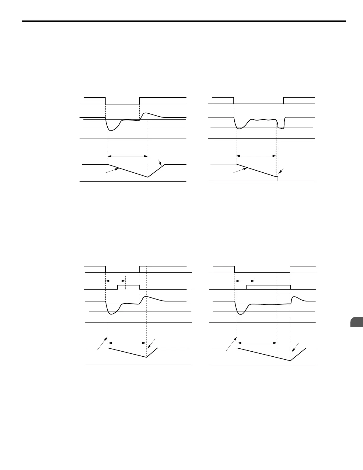
KEB Ride-Thru Operation in L2-02, Input Terminals Not Used
Here, L2-01 = 3 and the input terminals have not been set for KEB Ride-Thru (H1-oo does not equal 65, 66, 7A, 7B). After
decelerating for the time set in parameter L2-02, the drive ends KEB operation and attempts to accelerate back to the frequency
reference. A Uv1 fault occurs and the drive output shuts off if the power does not return within the time set to L2-02.
L2-11 (Desired DC Bus Voltage)
L2-05 (Uv Detection Level)
L2-11 (Desired DC
Bus Voltage)
L2-05 (Uv Detection Level)
0 Hz
L2-02
(Powe Loss
Ride-Thru Time)
0 V
0 V
KEB Deceleration
Acceleration using L2-07 or
C1-01/03/05/07 if L2-07 = 0
Power Loss shorter than L2-02
0 Hz
L2-02
(Powe Loss
Ride-Thru Time)
0 V
0 V
KEB Deceleration
Drive attempts to restart but
power has not returned
An Uv1 fault is triggered
Power Loss longer than L2-02
Power Loss
Power Loss
DC Bus Voltage
Main Power Supply
Output Frequency
Figure 5.91 KEB Operation Using L2-02, Without KEB Input
KEB Ride-Thru Operation Within L2-02, Input Terminals Used
Here, L2-01 = 3 and an input terminal is set to issue KEB Ride-Thru (H1-oo = 65, 66, 7A, 7B). After decelerating for the
time set in parameter L2-02, the drive checks the DC bus voltage and the status of the digital input. If the DC bus voltage is
still below the level set in L2-11 or if the KEB digital input is still active, KEB deceleration continues. If the voltage level has
risen above the value set to L2-11, then normal operation is resumed.
Note: If L2-10 is set to a longer time than L2-02, the drive checks the DC bus voltage level and the status of the terminal assigned to KEB Ride-Thru
after the time set to L2-02 passes. The drive will then try to restart.
L2-11 (Desired DC Bus Voltage)
0 Hz
DC bus voltage
0 V
0 V
KEB Digital Input
Main Power Supply
Output Frequency
L2-10
KEB deceleration is
triggered by DC bus voltage
KEB restart triggered by
digital input release
L2-02
(Powe Loss
Ride-Thur Time)
L2-05 (Uv Detection Level)
0 Hz
0 V
0 V
L2-10
KEB deceleration is
triggered by DC bus voltage
KEB restart after
L2-02 has passed
L2-02
(Powe Loss
Ride-Thur Time)
Power LossPower Loss
Power loss longer than L2-02Power loss shorter than L2-02
L2-05 (Uv Detection Level)
L2-11 (Desired DC Bus Voltage)
Figure 5.92 KEB Operation Using L2-02 and KEB Input
KEB Ride-Thru Operation as Long as CPU Has Power, KEB Input Not Used
Here, L2-01 = 4 and the input terminals have not been set for KEB Ride-Thru (H1-oo does not equal 65, 66, 7A, 7B). After
decelerating for the time set to parameter L2-10, the drive checks the DC bus voltage level. Deceleration continues if the DC
bus voltage is lower than the level set in L2-11. Normal operation resumes when the DC bus voltage rises above the value of
L2-11.
5.8 L: Protection Functions
YASKAWA ELECTRIC SIEP C710616 31B YASKAWA AC Drive – A1000 Technical Manual
245
5
Parameter Details

 Loading...


