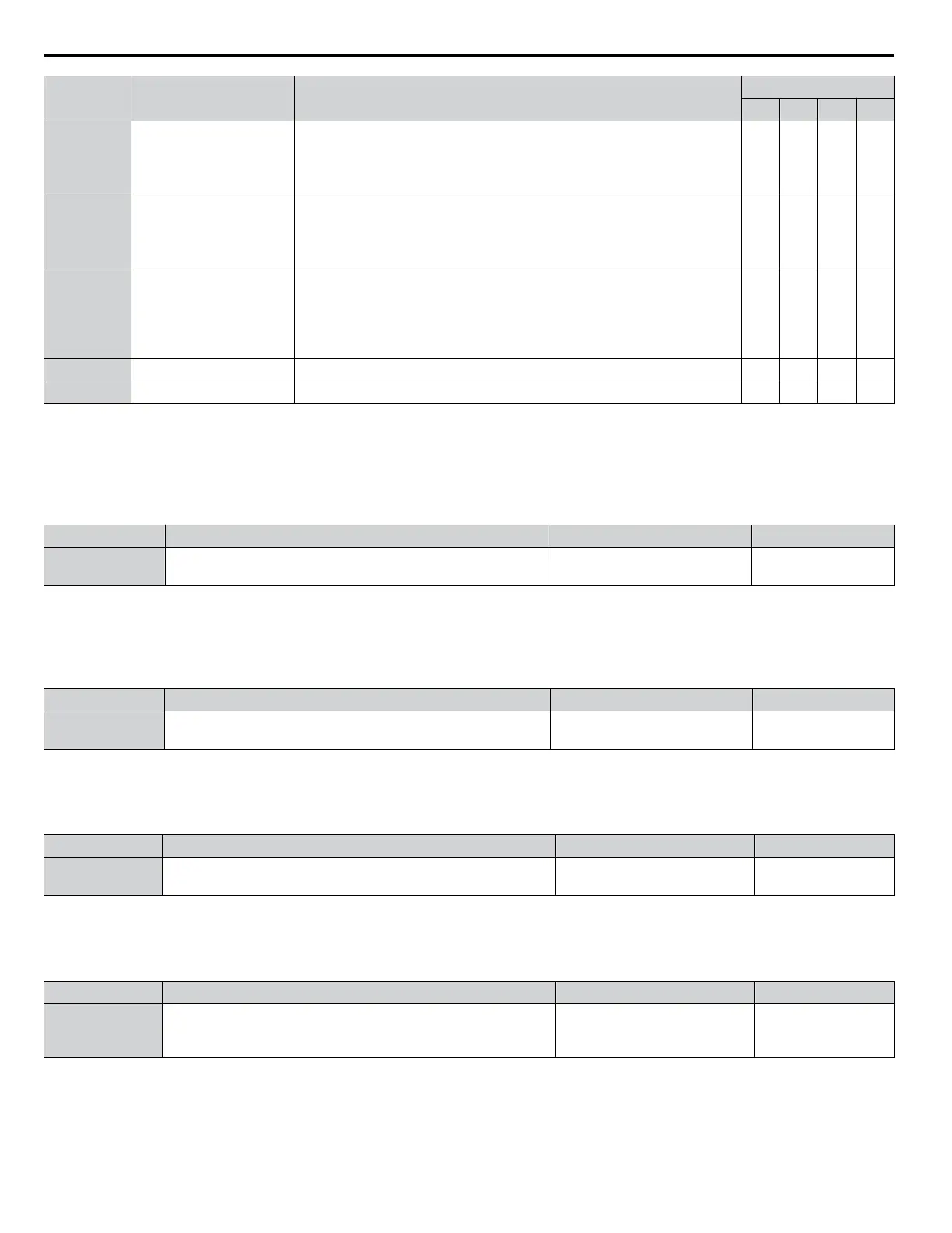
Parameter Name Setting Instructions
KEB Mode (L2-29)
0 1 2 3
L2-11
Desired DC Bus Voltage
during KEB
• Set to approximately 1.22 times the input voltage for Single Drive
KEB Ride-Thru 2.
• Set to approximately 1.4 times the input voltage for Single Drive KEB
Ride-Thru 1 and System KEB Ride-Thru modes.
YES YES YES YES
L3-20
Main Circuit Adjustment
Gain
• Increase this setting in steps of 0.1 if overvoltage or undervoltage
occurs at the beginning of deceleration
• Reduce if torque ripple occurs during deceleration while executing
KEB Ride-Thru.
NO YES NO NO
L3-21
Accel/Decel Rate
Calculation Gain
• Reduce L3-21 in steps of 0.05 if there is a fairly large speed or current
ripple.
• Decreasing this setting too much can cause a slow DC bus voltage
control response, and may lead to problems with overvoltage or
undervoltage.
NO YES NO NO
L3-24 Motor Acceleration Time Set the motor acceleration time as described on page 255. NO YES NO NO
L3-25 Load Inertia Ratio Set the load/inertia ratio as described on page 255. NO YES NO NO
n
L2-02: Momentary Power Loss Ride-Thru Time
Sets the maximum time allowed to ride through a power loss. If power loss operation exceeds this time, the drive will attempt
to accelerate back to the frequency reference. This parameter is valid if L2-01 = 1 or 3.
Note: The amount of time the drive is capable of recovering after a power loss is determined by the capacity of the drive. Drive capacity determines
the upper limit for L2-02.
No. Name Setting Range Default
L2-02 Momentary Power Loss Ride-Thru Time 0.0 to 25.5 s
Determined by C6-01
and o2-04
n
L2-03: Momentary Power Loss Minimum Baseblock Time
Sets the minimum baseblock time when power is restored following a momentary power loss. This determines the time the
drive waits for the residual voltage in the motor to dissipate. Increase this setting if overcurrent or overvoltage occurs at the
beginning of Speed Search, after a power loss, or during DC Injection Braking.
No. Name Setting Range Default
L2-03 Momentary Power Loss Minimum Baseblock Time 0.1 to 5.0 s
Determined by C6-01
and o2-04
n
L2-04: Momentary Power Loss Voltage Recovery Ramp Time
Sets the time for the drive to restore the output voltage to the level specified by the V/f pattern after Speed Search. The setting
value determines the time for the voltage to go from 0 V to the maximum voltage.
No. Name Setting Range Default
L2-04 Momentary Power Loss Voltage Recovery Ramp Time 0.0 to 5.0 s
Determined by
C6-01 and o2-04
n
L2-05: Undervoltage Detection Level (Uv1)
Determines the voltage at which a Uv1 fault is triggered or at which the KEB function is activated. This setting rarely needs
to be changed.
No. Name Setting Range Default
L2-05 Undervoltage Detection Level 431.3 to 603.8 Vdc
Determined by
A1-02, C6-01, E1-01
and o2-04
Note: 1. Install an AC reactor option on the input side of the power supply when setting L2-05 below the default value to prevent damage to drive
circuitry.
2. If using KEB Ride-Thru and L2-05 is set too low, then undervoltage in the DC bus (uv1) will be triggered before KEB Ride-Thru can be
executed. Take caution not to set this value too low.
5.8 L: Protection Functions
248
YASKAWA ELECTRIC SIEP C710616 31B YASKAWA AC Drive – A1000 Technical Manual

 Loading...


