n
KEB Operation Wiring Example
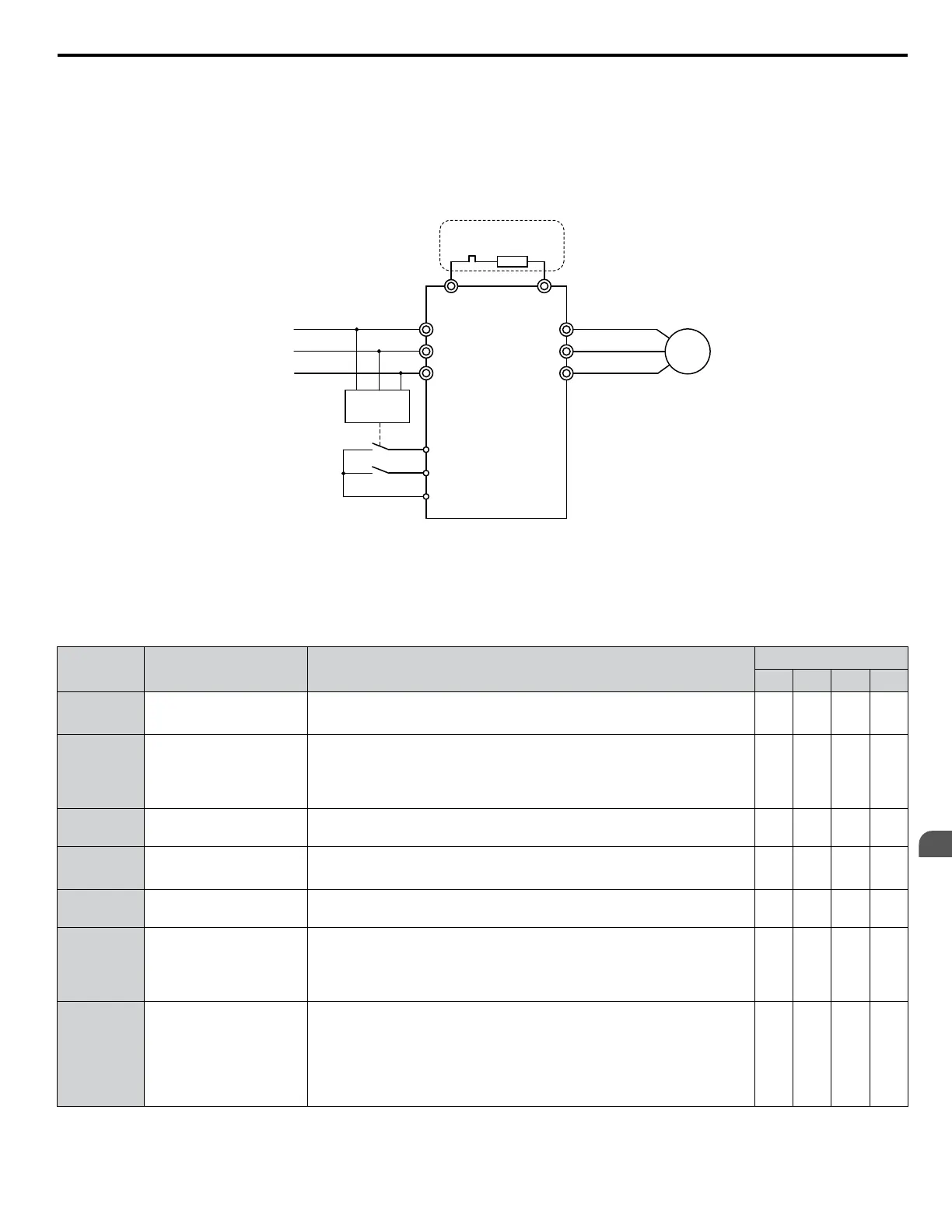
Figure 5.95 shows a wiring example to trigger the KEB Ride-Thru at power loss using an undervoltage relay. When a power
loss occurs, the undervoltage relay triggers KEB Ride-Thru at terminal S6 (H1-06 = 65, 66, 7A, 7B). Note that using System
KEB Ride-Thru requires an additional dynamic braking option.
Note: 1. Do not switch off the Run command during momentary power loss. If the Run command is shut off, the drive will not accelerate back to
speed when the power is restored.
2. A dynamic braking option is required to use System KEB 1 (L2-29 = 2).
M
R/L1
S/L2
T/L3
U/T1
V/T2
W/T3
B1 B2
L1
L2
L3
Braking
Resistor
UV Detection
Relay
S6 - KEB command 1 or 2
S1 - Start command
SC
Required for System KEB
Ride-Thru 1 only (L2-29 = 2)
Figure 5.95 KEB Function Wiring Example
n
Parameters for KEB Ride-Thru
Table 5.36 lists parameters needed to set up KEB Ride-Thru depending the type of KEB Ride-Thru selected in L2-29.
Table 5.36 KEB Function Related Adjustments
Parameter Name Setting Instructions
KEB Mode (L2-29)
0 1 2 3
C1-09 Fast Stop Time
• Increase if an overvoltage fault occurs during KEB deceleration.
• Decrease if an undervoltage fault occurs during KEB deceleration.
YES NO NO NO
C2-03
S-Curve at Deceleration
Start
• Shorten if undervoltage occurs immediately after KEB Ride-Thru is
triggered.
• Lengthen this setting if overvoltage occurs immediately after KEB
operation starts.
YES NO YES YES
L2-05
Undervoltage Detection
Level
Increase if an undervoltage fault occurs at KEB operation start to let the
drive detect power loss more quickly.
YES YES YES YES
L2-06 KEB Deceleration Time
• Increase if an overvoltage fault occurs during KEB deceleration
• Decrease if an undervoltage fault occurs during KEB deceleration
NO NO YES YES
L2-07 KEB Acceleration Time
Adjust to the desired acceleration time. If set to 0, standard acceleration
times are used (C1-01, C1-03, C1-05, C1-07).
YES YES YES YES
L2-08
Frequency Gain at KEB
Start
• Increase if an undervoltage fault occurs immediately after KEB
operation starts.
• Decrease if an overvoltage fault occurs immediately after KEB
operation starts.
YES NO YES YES
L2-10 KEB Detection Time
• Increase when a digital input is set for KEB Ride-Thru and an
undervoltage fault occurs after power was lost because the device
controlling the input does not react quickly enough.
• If the DC bus voltage overshoots after KEB Ride-Thru begins (and
no input terminal is set to KEB Ride-Thru), increase L2-10 to longer
than the overshoot.
YES YES YES YES
5.8 L: Protection Functions
YASKAWA ELECTRIC SIEP C710616 31B YASKAWA AC Drive – A1000 Technical Manual
247
5
Parameter Details

 Loading...


