PG cable is disconnected Reconnect the cable.
Digital Operator Display Fault Name
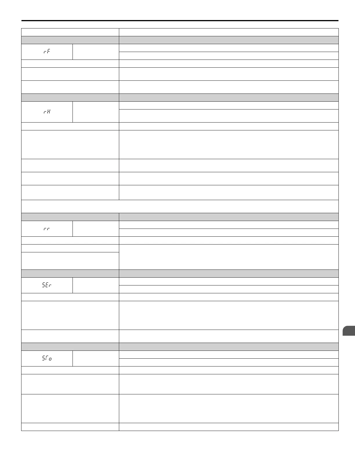
rF
Braking Resistor Fault
The resistance of the braking resistor is too low.
Cause Possible Solution
The proper braking resistor option has not
been installed
Select the braking resistor option so that fits to the drives braking transistor specification.
Regenerative converter, regenerative unit, or
braking unit is being used
Set L8-55 to 0 to disable the braking transistor protection selection.
Digital Operator Display Fault Name
rH
Braking Resistor Overheat
Braking resistor protection was triggered.
Fault detection is enabled when L8-01 = 1 (disabled as a default).
Cause Possible Solution
Deceleration time is too short and excessive
regenerative energy is flowing back into the
drive
• Check the load, deceleration time, and speed.
• Reduce the load inertia.
• Increase the deceleration times (C1-02, C1-04, C1-06, C1-08, C1-09).
• Replace the dynamic braking option with a larger device that can handle the power that is discharged.
Excessive braking inertia
Recalculate braking load and braking power. Reduce the braking load by adjusting braking resistor
settings.
The braking operation duty cycle is too high
Check the braking operation duty cycle. Braking resistor protection for ERF-type braking resistors (L8-01
= 1) allows a braking duty cycle of maximum 3%.
The proper braking resistor has not been
installed
• Check the specifications and conditions for the braking resistor device.
• Select the optimal braking resistor.
Note: The magnitude of the braking load trips the braking resistor overheat alarm, NOT the surface temperature. Using the braking resistor more
frequently than it is rated for trips the alarm even when the braking resistor surface is not very hot.
Digital Operator Display Fault Name
rr
Dynamic Braking Transistor
The built-in dynamic braking transistor failed.
Cause Possible Solution
The braking transistor is damaged • Cycle power to the drive and check if the fault reoccurs. Refer to Diagnosing and Resetting Faults
on page 334.
• Replace either the control board or the entire drive. For instructions on replacing the control board,
contact Yaskawa or a Yaskawa representative.
The control circuit is damaged
Digital Operator Display Fault Name
SEr
Too Many Speed Search Restarts
The number of Speed Search restarts exceeded the value set to b3-19.
Cause Possible Solution
Speed Search parameters are set to the wrong
values
• Reduce the detection compensation gain during Speed Search (b3-10).
• Increase the current level when attempting Speed Search (b3-17).
• Increase the detection time during Speed Search (b3-18).
• Repeat Auto-Tuning.
The motor is coasting in the opposite direction
of the Run command
Enable Bi-Directional Speed Search (b3-14 = 1).
Digital Operator Display Fault Name
STo
Motor Pull Out or Step Out Detection
Motor pull out or step out has occurred. Motor has exceeded its pull-out torque.
Cause Possible Solution
The wrong motor code is set (Yaskawa motors
only)
• Enter the correct motor code for the PM being used into E5-01.
• For special-purpose motors, enter the correct data to all E5 parameters according to the test report
provided for the motor.
Load is too heavy
• Increase the load inertia for PM motor (n8-55).
• Increase the pull-in current during accel/decel (n8-51).
• Reduce the load.
• Increase the motor or drive capacity.
Load inertia is too heavy Increase the load inertia for PM motor (n8-55).
6.4 Fault Detection
YASKAWA ELECTRIC SIEP C710616 31B YASKAWA AC Drive – A1000 Technical Manual
313
6
Troubleshooting

 Loading...


