Acceleration and deceleration times are too
short
• Increase the acceleration and deceleration times (C1-01 through C1-08).
• Increase the S-curve acceleration and deceleration times (C2-01).
Speed response is too slow Increase the load inertia for PM motor (n8-55).
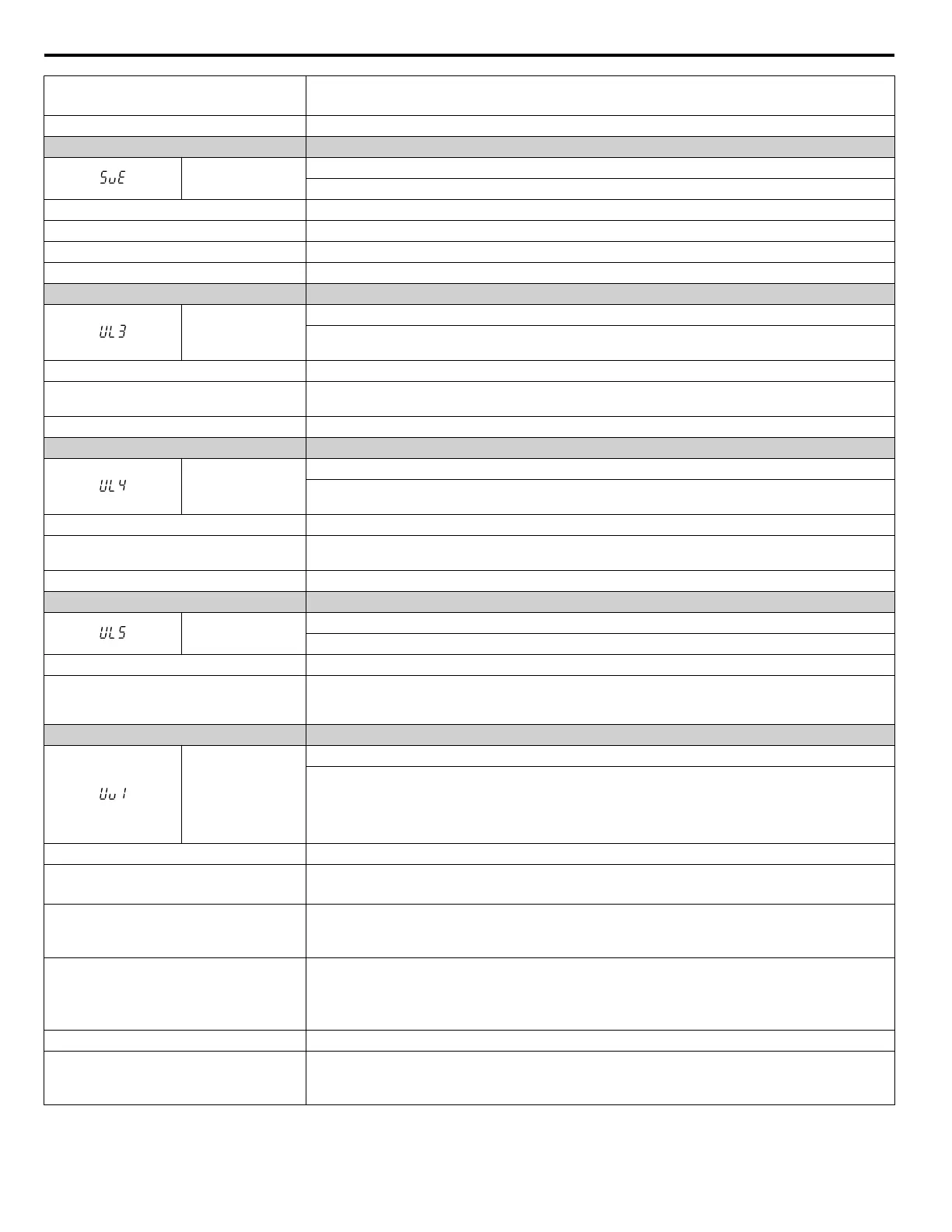
Digital Operator Display Fault Name
SvE
Zero Servo Fault
Position deviation during zero servo.
Cause Possible Solution
Torque limit is set too low Set the torque limit to an appropriate value using parameters L7-01 to L7-04.
Excessive load torque Reduce the amount of load torque.
Noise interference along PG encoder wiring Check the PG signal for noise interference.
Digital Operator Display Fault Name
UL3
Undertorque Detection 1
The current has fallen below the minimum value set for torque detection (L6-02) for longer than the
allowable time (L6-03).
Cause Possible Solution
Parameter settings are not appropriate for the
load
Check the settings of parameters L6-02 and L6-03.
There is a fault on the machine side Check the load for any problems.
Digital Operator Display Fault Name
UL4
Undertorque Detection 2
The current has fallen below the minimum value set for torque detection (L6-05) for longer than the
allowable time (L6-06).
Cause Possible Solution
Parameter settings are not appropriate for the
load
Check the settings of parameters L6-05 and L6-06.
There is a fault on the machine side Check the load for any problems.
Digital Operator Display Fault Name
UL5
Mechanical Weakening Detection 2
The operation conditions matched the conditions set to L6-08.
Cause Possible Solution
Undertorque was detected and matched the
conditions for mechanical loss detection set to
L6-08
Check the load side for any problems.
Digital Operator Display Fault Name
Uv1
DC Bus Undervoltage
Voltage in the DC bus fell below the undervoltage detection level (L2-05).
Refer to the Undervoltage Protection row in the A.3 Drive Specifications section on page 374 for detection
level values.
The fault is output only if L2-01 = 0 or L2-01 = 1 and the DC bus voltage has fallen below the level set
to L2-05 for longer than the time set to L2-02.
Cause Possible Solution
Input power phase loss
• The main circuit drive input power is wired incorrectly.
• Correct the wiring.
One of the drive input power wiring terminals
is loose
• Ensure there are no loose terminals.
• Apply the tightening torque specified in this manual to fasten the terminals. Refer to Wire Gauges
and Tightening Torque on page 58.
There is a problem with the voltage from the
drive input power
• Check the voltage.
• Correct the voltage to be within the range listed in drive input power specifications.
• If there is no problem with the power supply to the main circuit, check for problems with the main
circuit magnetic contactor.
The power has been interrupted Correct the drive input power.
The main circuit capacitors are worn
• Check the maintenance time for the capacitors (U4-05).
• Replace either the control board or the entire drive if U4-05 exceeds 90%. For instructions on replacing
the control board, contact Yaskawa or a Yaskawa representative.
6.4 Fault Detection
314
YASKAWA ELECTRIC SIEP C710616 31B YASKAWA AC Drive – A1000 Technical Manual

 Loading...


