n
Single Drive Installation
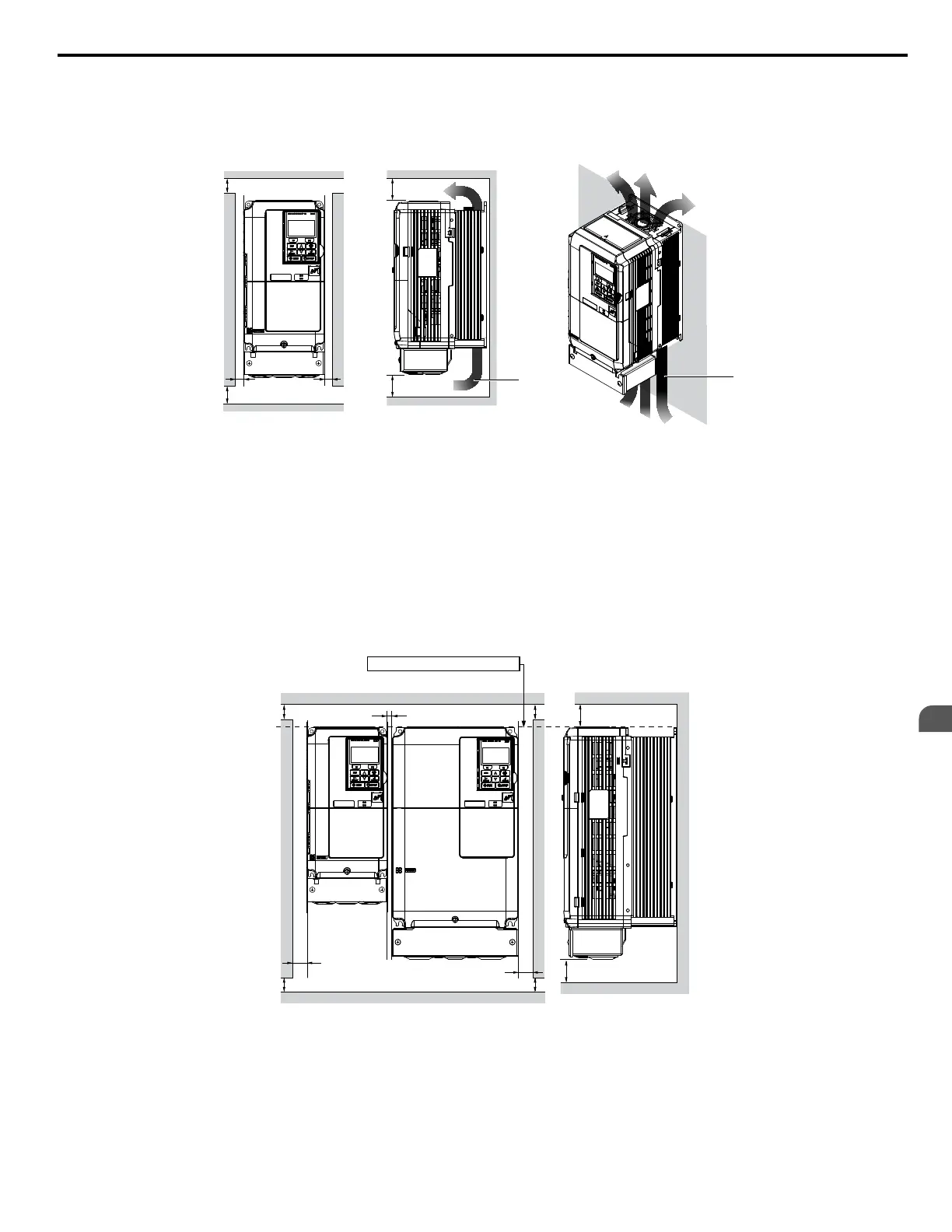
Figure 2.2 shows the installation distance required to maintain sufficient space for airflow and wiring. Install the heatsink
against a closed surface to avoid diverting cooling air around the heatsink.
A
A
B B
Side Clearance Top/Bottom Clearance
C
C
D
D
A – 50 mm minimum
B – 30 mm minimum
C – 120 mm minimum
D – Airflow direction
Figure 2.2 Correct Installation Spacing
Note: IP20/NEMA Type 1 and IP00/Open-Chassis models require the same amount of space above and below the drive for installation.
n
Multiple Drive Installation (Side-by-Side Installation)
Models CIMR-Ao5A0003 through 0011 can take advantage of Side-by-Side installation.
When installing multiple drives into the same enclosure panel, mount the drives according to Figure 2.2.
When mounting drives with the minimum clearance of 2 mm according to Figure 2.3, set parameter L8-35 to 1 while
considering derating. Refer to Temperature Derating on page 377.
A
A
A
A
B
C
B
Side Clearance
Line up the tops of the drives.
D
D
Top/Bottom Clearance
A – 50 mm minimum
B – 30 mm minimum
C – 2 mm minimum
D – 120 mm minimum
Figure 2.3 Space Between Drives (Side-by-Side Mounting)
Note: Align the tops of the drives when installing drives of different heights in the same enclosure panel. Leave space between the tops and bottoms
of stacked drives for easier cooling fan replacement.
Remove the top protective covers of all drives as shown in Figure 2.4 when mounting IP20/NEMA Type 1 drives side-by-
side. Refer to Top Protective Cover on page 57 to remove and reattach the top protective cover.
2.2 Mechanical Installation
YASKAWA ELECTRIC SIEP C710616 31B YASKAWA AC Drive – A1000 Technical Manual
41
2
Mechanical Installation

 Loading...


