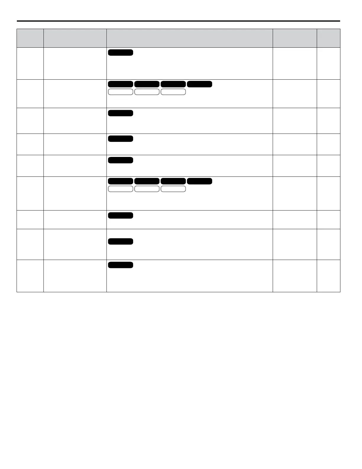
No.
(Addr.
Hex)
Name Description Values Page
L2-03
(487)
Momentary Power Loss
Minimum Baseblock Time
All Modes
Sets the minimum wait time for residual motor voltage decay before the drive
output reenergizes after performing Power Loss Ride-Thru.
Increasing the time set to L2-03 may help if overcurrent or overvoltage occur
during Speed Search or during DC Injection Braking.
Default:
<1>
Min.: 0.1 s
Max.: 5.0 s
248
L2-04
(488)
Momentary Power Loss
Voltage Recovery Ramp
Time
V/f
OLV/PM
V/f w PG
AOLV/PM
OLV
CLV/PM
CLVV/f V/f w PG OLV CLVV/f
OLV/PM
V/f w PG
AOLV/PM
OLV
CLV/PM
CLVV/f V/f w PG OLV CLV
Sets the time for the output voltage to return to the preset V/f pattern during
Speed Search.
Default:
<1>
Min.: 0.0 s
Max.: 5.0 s
248
L2-05
(489)
Undervoltage Detection
Level (Uv1)
All Modes
Sets the DC bus undervoltage trip level.
Default: 500.0 Vdc
<2>
Min.: 431.3
Max.: 603.8
248
L2-06
(48A)
KEB Deceleration Time
All Modes
Sets the time required to decelerate from the speed when KEB was activated
to zero speed.
Default: 0.00 s
Min.: 0.00
Max.: 6000.0
<3>
249
L2-07
(48B)
KEB Acceleration Time
All Modes
Sets the time to accelerate to the frequency reference when momentary power
loss is over. If set to 0.0, the active acceleration time is used.
Default: 0.00 s
Min.: 0.00
Max.: 6000.0
<3>
249
L2-08
(48C)
Frequency Gain at KEB
Start
V/f
OLV/PM
V/f w PG
AOLV/PM
OLV
CLV/PM
CLVV/f V/f w PG OLV CLVV/f
OLV/PM
V/f w PG
AOLV/PM
OLV
CLV/PM
CLVV/f V/f w PG OLV CLV
Sets the percentage of output frequency reduction at the beginning of
deceleration when the KEB Ride-Thru function is started.
Reduction = (slip frequency before KEB) × L2-08 × 2
Default: 100%
Min.: 0
Max.: 300
249
L2-10
(48E)
KEB Detection Time
(Minimum KEB Time)
All Modes
Sets the time to perform KEB Ride-Thru.
Default: 50 ms
Min.: 0
Max.: 2000
249
L2-11
(461)
DC Bus Voltage Setpoint
during KEB
All Modes
Sets the desired value of the DC bus voltage during KEB Ride-Thru.
Default: 661.3 Vdc
<2>
[E1-01] × 1.22
Min.: 431.3
Max.: 1150
249
L2-29
(475)
KEB Method Selection
All Modes
0: Single Drive KEB Ride-Thru 1
1: Single Drive KEB Ride-Thru 2
2: System KEB Ride-Thru 1
3: System KEB Ride-Thru 2
Default: 0
Range: 0 to 3
249
<1> Default setting is dependent on parameters C6-01, Drive Duty Selection, and o2-04, Drive Model Selection.
<2> Default setting is dependent on parameter E1-01, Input voltage Setting.
<3> Setting range value is dependent on parameter C1-10, Accel/Decel Time Setting Units. When C1-10 = 0 (units of 0.01 seconds), the setting range
becomes 0.00 to 600.00 seconds.
B.10 L: Protection Function
428
YASKAWA ELECTRIC SIEP C710616 31B YASKAWA AC Drive – A1000 Technical Manual

 Loading...


