Type No. Terminal Name (Function) Function (Signal Level) Default Setting Page
Analog Inputs /
Pulse Train
Input
RP
Multi-function pulse train input (Frequency
reference)
Input frequency range: 0 to 32 kHz
Signal Duty Cycle: 30 to 70%
High level: 3.5 to 13.2 Vdc, low level: 0.0 to 0.8 Vdc
Input impedance: 3 kΩ
127
235
+V Power supply for analog inputs 10.5 Vdc (max allowable current 20 mA) 126
-V Power supply for analog inputs -10.5 Vdc (max allowable current 20 mA) –
A1
Multi-function analog input 1 (Frequency
reference bias)
-10 to 10 Vdc, 0 to 10 Vdc (input impedance: 20 kΩ)
126
228
A2
Multi-function analog input 2 (Frequency
reference bias)
-10 to 10 Vdc, 0 to 10 Vdc (input impedance: 20 kΩ)
4 to 20 mA, 0 to 20 mA (input impedance: 250 Ω)
Voltage or current input must be selected by DIP switch S1 and H3-09
126
126
230
A3
Multi-function analog input 3 (auxiliary
frequency reference)/PTC Input
-10 to 10 Vdc, 0 to 10 Vdc (input impedance: 20 kΩ)
Use DIP switch S4 on the terminal board to select between analog and
PTC input.
126
AC Frequency reference common 0 V 126
E (G) Ground for shielded lines and option cards – –
<1> Terminals H1, H2, DM+, and DM- on 600 V class models are designed to the functionality, but are not certified to EN61800-5-1, EN954-1/ISO13849
Cat. 3, IEC/EN61508 SIL2, Insulation coordination: class 1.
n
Output Terminals
Table 3.5 lists the output terminals on the drive. Text in parenthesis indicates the default setting for each multi-function output.
Table 3.5 Control Circuit Output Terminals
Type No. Terminal Name (Function) Function (Signal Level) Default Setting Page
Fault Relay
MA N.O.
30 Vdc, 10 mA to 1 A; 250 Vac, 10 mA to 1 A
Minimum load: 5 Vdc, 10 mA
218MB N.C. output
MC Fault output common
Multi-Function
Digital Output
<1>
M1
Multi-function digital output (During run)
30 Vdc, 10 mA to 1 A; 250 Vac, 10 mA to 1 A
Minimum load: 5 Vdc, 10 mA
218
M2
M3
Multi-function digital output (Zero speed)
M4
M5
Multi-function digital output (Speed Agree 1)
M6
Monitor
Output
MP Pulse train output (Output frequency) 32 kHz (max) 235
FM Analog monitor output 1 (Output frequency)
-10 to +10 Vdc, or 0 to +10 Vdc 234
AM Analog monitor output 2 (Output current)
AC Monitor common 0 V –
Safety Monitor
Output
<2>
DM+ Safety monitor output
Outputs status of Safe Disable function. Closed when both Safe
Disable channels are closed. Up to +48 Vdc 50 mA
503
DM- Safety monitor output common
<1> Refrain from assigning functions to digital relay outputs that involve frequent switching, as doing so may shorten relay performance life. Switching
life is estimated at 200,000 times (assumes 1 A, resistive load).
<2> Terminals H1, H2, DM+, and DM- on 600 V class models are designed to the functionality, but are not certified to EN61800-5-1, EN954-1/ISO13849
Cat. 3, IEC/EN61508 SIL2, Insulation coordination: class 1.
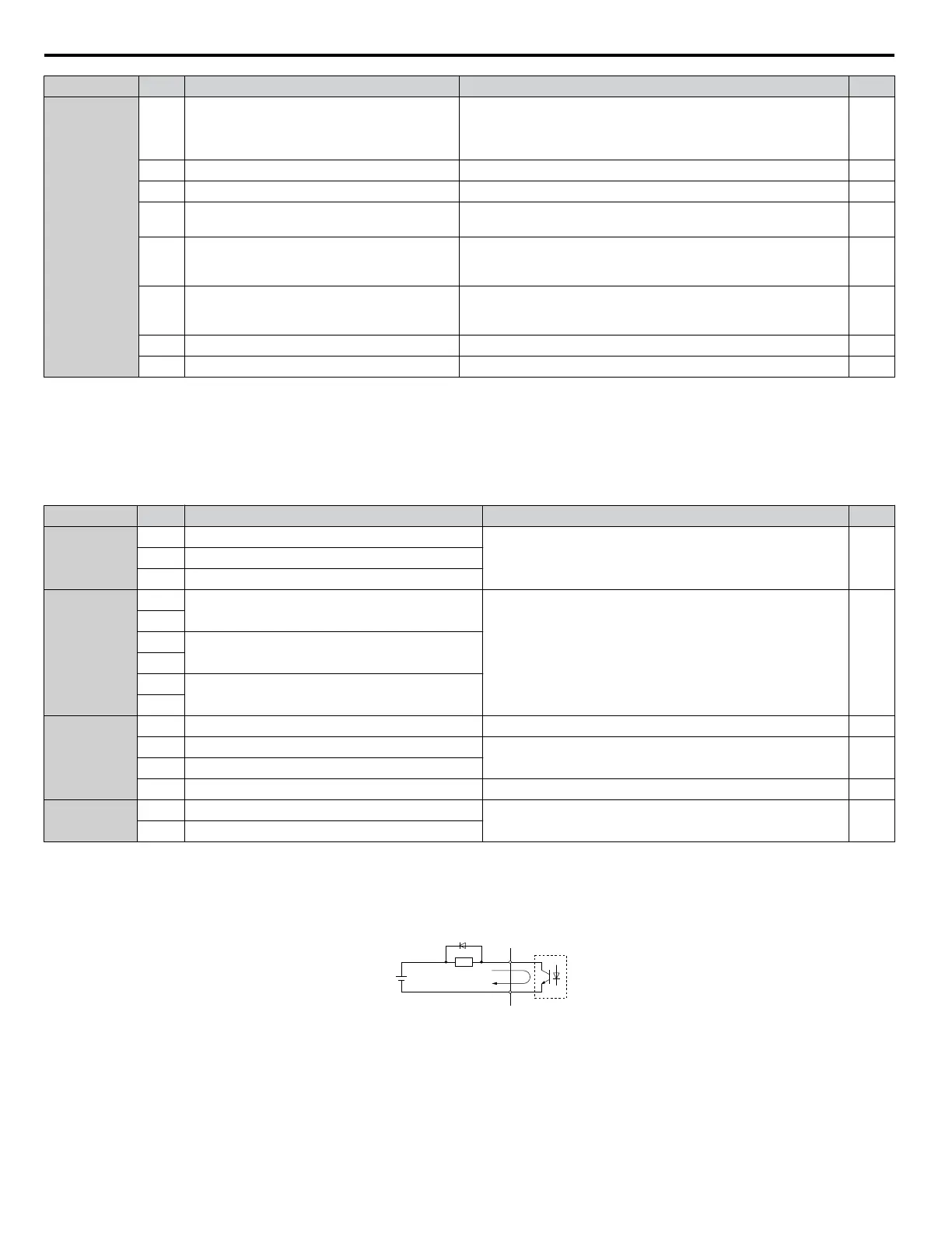
A
B
C
D
A – External power, 48 V max.
B – Suppression diode
C – Coil
D – 50 mA or less
Figure 3.14 Connecting a Suppression Diode
3.9 Control Circuit Wiring
62
YASKAWA ELECTRIC SIEP C710616 31B YASKAWA AC Drive – A1000 Technical Manual

 Loading...


