www.dadehpardazan.ir 88594014-15
5.11 Safety Function
5-83
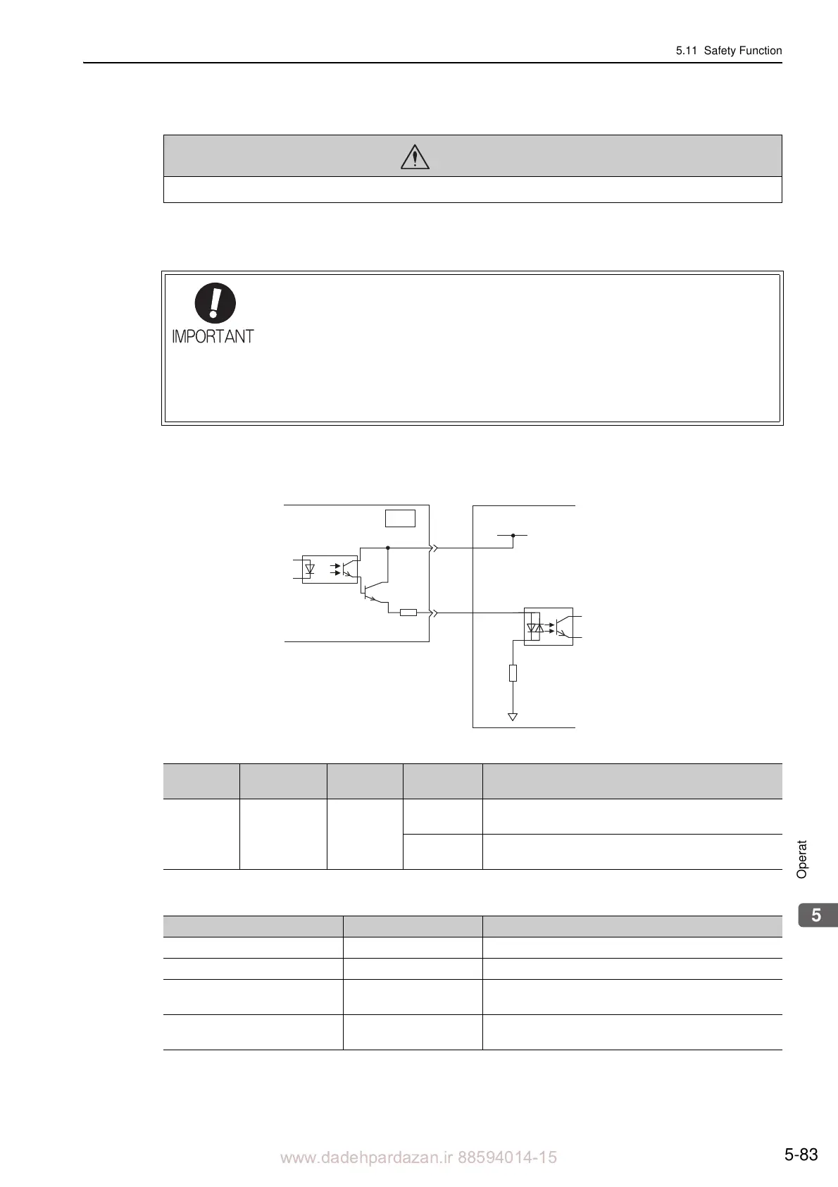
(1) Connection Example and Specifications of EDM1 Output Signal
Connection example and specifications of EDM1 output signal are explained below.
Connection Example
EDM1 output signal is used for source circuit.
Specifications
Electrical characteristics of EDM1 signal are as follows.
WARNING
• The EDM1 signal is not a safety output. Use it only for monitoring a failure.
For safety function signal connections, the input signal is the 0 V common and the output
signal is the source output. This is opposite to other signals described in this manual. To
avoid confusion, the ON and OFF status of signals for safety functions are defined as fol
-
lows:
ON: The state in which the relay contacts are cl
osed or the transistor is ON and current
flows into the signal line.
OFF: The state in which the relay contacts are
open or the transistor is OFF and no cur-
rent flows into the signal line.
Host controller
EDM1+
CN8
EDM1-
8
7
0 V
24-V power supply
SERVOPACK
Type
Signal
Name
Connector
Pin Number
Setting Meaning
Output EDM1
CN8-8
CN8-7
ON (closed)
Both the /HWBB1 and the /HWBB2 signals are working
n
ormally.
OFF (open)
The /HWBB1 signal, the /HWBB2 signal or both are not
working normally.
Items Characteristics Remarks
Maximum Allowable Voltage 30 VDC
Maximum Current 50 mADC
Maximum Voltage Drop at ON 1.0 V
Voltage between EDM1+ and EDM1- when current is 50
mA
Maximum Delay Time 20 ms
Time from the change in /HWBB1 or /HWBB2 until the
change
in EDM1
 Loading...


