www.dadehpardazan.ir 88594014-15
3.1 Main Circuit Wiring
3-5
(3) Typical Main Circuit Wiring Examples
Note the following points when designing the power ON sequence.
• Design the power ON sequence so that main power is turned OFF when a servo alarm signal (ALM) is output.
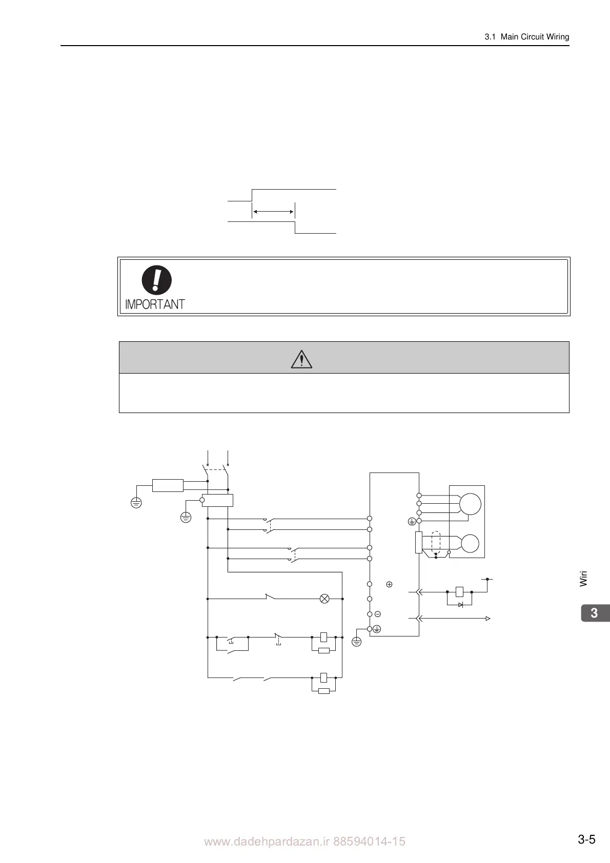
• The ALM signal is output for a maximum of five seconds when the
control power is turned ON. Take this into consid-
eration when designing the power ON sequence.
Design the sequence so the ALM signal is activated and the alarm
detection relay (1Ry) is turned OFF to stop the main circuit’s power supply to the SERVOPACK.
• Select the power supply specifications for the parts in accordance with the input power supply.
The typical main circuit wiring examples are shown below.
Single-phase 100 V, SGDV-F (SGDV-R70F, -R90F, -2R1F, -2R8F)
• When turning ON the control power supply and the main circuit power supply, turn
them ON at the same time or turn the main circuit power supply after the control
power supply. When turning OFF the power supplies, first turn the power for the main
circuit OFF and then turn OFF the control power supply.
WARNING
• Do not touch the power supply terminals after turning OFF the power. High voltage may still remain in the
SERVOPACK, resulting in electric shock. When the voltage is discharged, the charge indicator will turn
OFF. Make sure the charge indicator is OFF before starting wiring or inspections.
Control power supply
ALM signal
5.0 s max.
L1
ENC
U
V
W
M
0 V
1Ry
+
−
31
32
1D
2KM
1KM
B2
L2
CN1
1QF
R T
+24 V
B1/
3SA
1Ry
1PL
1KM
2KM
1SA
1KM
1Ry
1KM
2SA
L1C
L2C
ALM
ALM
1FLT
1PL: Indicator lamp
1SA: Surge absorber
2SA: Surge absorber
3SA: Surge absorber
1D: Flywheel diode
1QF: Molded-case circuit breaker
1FLT: Noise filter
1KM: Magnetic contactor (for control power supply)
2KM: Magnetic contactor (for main circuit power supply)
1Ry: Relay
SERVOPACK
SGDV-F
(For servo
alarm display)
supply ON
Servo power
supply OFF
Servo power