www.dadehpardazan.ir 88594014-15
3.1 Main Circuit Wiring
3-9
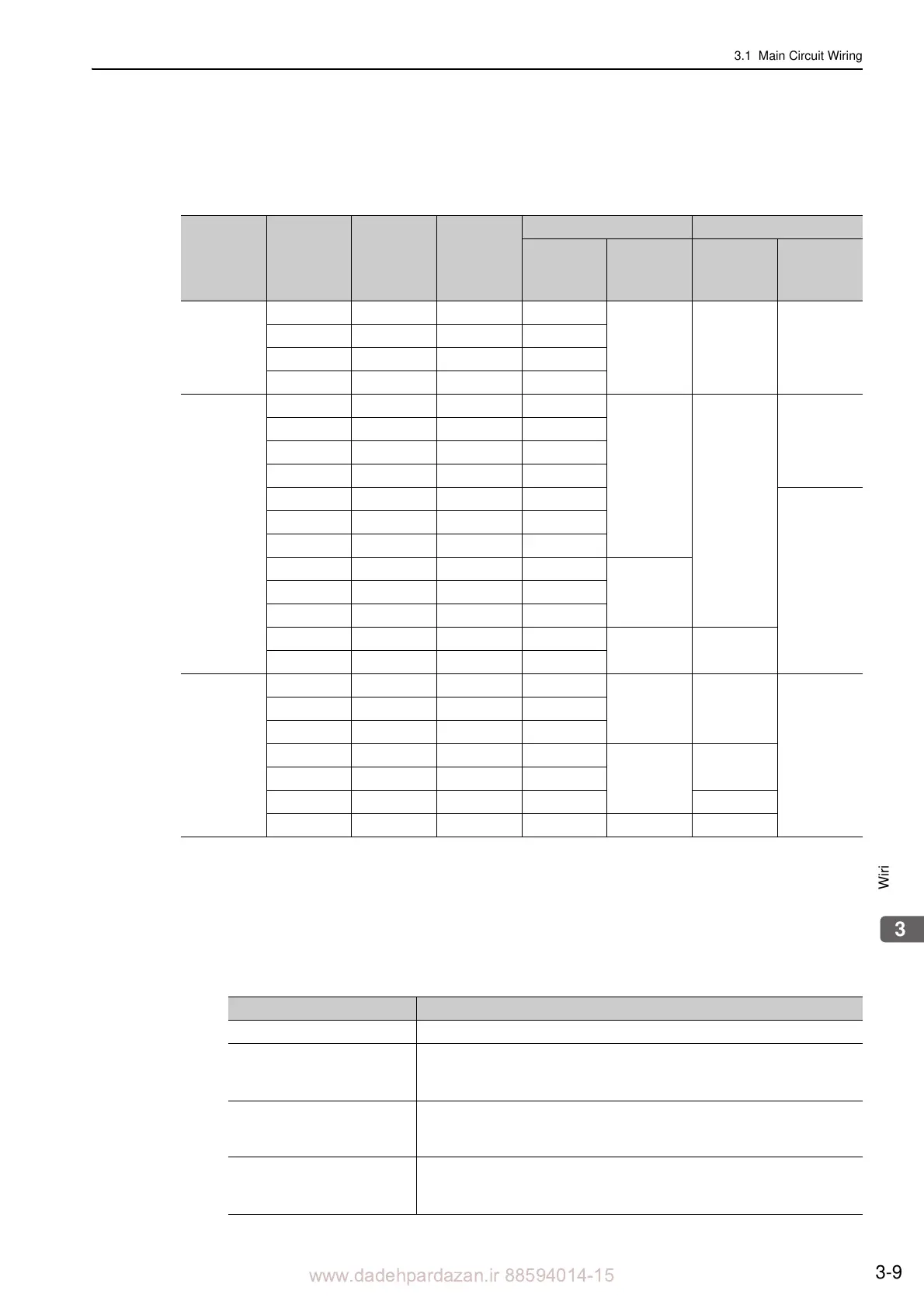
(5) How to Select Molded-case Circuit Breaker and Fuse Capacities
The following table shows the SERVOPACK’s current capacities and inrush current.
Select a molded-case circuit breaker and fuses in accordance with thes
e specifications.
Note 1. To comply with the EU low voltage directive, connect a fuse to the input side as protection against accidents
caused by short-circuits.
Select fuses or molded-case circuit breakers that are compliant with UL standards.
The table above also provides the net values of current capacity and inrush current. Select a fuse and a molded-
case circuit breaker which meet the breaking characteristics shown below.
• Main circuit, control circuit: No breaking at three times the current values shown in the table for 5 s.
• Inrush current: No breaking at the current values shown in the table for 20 ms.
2. The following restrictions apply to UL standard compliance conditions.
Main
Circuit
Power
Supply
Maximum
Applicable
Servomotor
Capacity
[kW]
SERVO-
PACK
Model
SGDV-
Power Sup-
ply Capacity
per SER-
VOPACK
[kVA]
Current Capacity Inrush Current
Main Circuit
[Arms]
Control
Circuit
[Arms]
Main Circuit
[A0-p]
Control
Circuit
[A0-p]
Single-
pha
se,
100 V
0.05 R70F 0.2 1.5
0.38 16.5 35
0.1 R90F 0.3 2.5
0.2 2R1F 0.7 5
0.4 2R8F 1.4 10
Three-
pha
se,
200 V
0.05 R70A 0.2 1.0
0.2
33
70
0.1 R90A 0.3 1.0
0.2 1R6A 0.6 2.0
0.4 2R8A 1 3.0
0.5 3R8A 1.4 3.0
33
0.75 5R5A 1.6 6.0
1.0 7R6A 2.3 6.0
1.5 120A 3.2 7.3
0.252.0 180A 4 9.7
3.0 200A 5.9 15
5.0 330A 7.5 25
0.3 65.5
7.5 550A 14.6 37
Three-
pha
se,
400 V
0.5 1R9D 1.1 1.4
1.2 17
–
1.0 3R5D 2.3 2.9
1.5 5R4D 3.5 4.3
2.0 8R4D 4.5 5.8
1.4
34
3.0 120D 7.1 8.6
5.0 170D 11.7 14.5 57
7.5 260D 14.4 21.7 1.5 34
SERVOPACK Model SGDV- Restrictions
180A, 200A Available rated current for modeled-ca
se circuit breaker: 40 A or less
330A
• Available rated current for non-time
delay fuse: 70 A or less
• Available rated current for time delay fuse: 40 A
or less
• Do not use single wires.
550A
• Available rated current for molded-cas
e circuit breaker: 60 A or less
• Available rated current for non-time delay fuse or time delay fuse: 60 A or
less
260D
• Available rated current for molded-case circuit breaker: 60 A or less.
• Available rated current for non-time-delay fuse: 60 A or less.
• Available rated current for time delay fuse: 35 A or less

 Loading...


