www.dadehpardazan.ir 88594014-15
3 Wiring and Connection
3.5.2 Serial Converter Unit
3-38
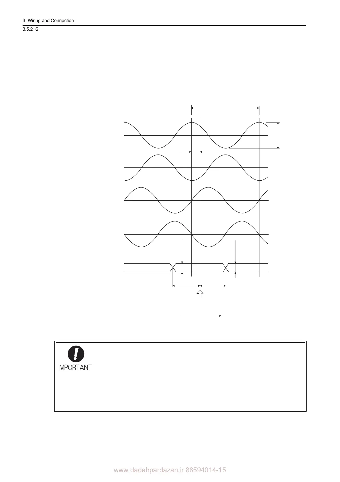
(3) Analog Signal Input Timing
The following figure shows the input timing of the analog signals.
When the cos and sin signals are shifted 180 degrees, the dif
ferential signals are produced as the /cos and /sin
signals. The specifications of the cos, /cos, sin, and /sin signals are identical except for the phase.
Input the signals Ref and /Ref so that th
ey shall cross each other as shown in the figure because they are input
into the comparator of the serial converter unit. When they are crossed, the output data will be counted up.
If the analog signal amplitude declines to about 0.35 V because of differential amplitude, the serial converter unit out-
puts an alarm.
• Never perform insulation resistance and withstand voltage tests.
• When low-voltage analog signals are input to the serial converter unit, noise influence
on th
e analog signals affects the unit’s ability to output correct position information.
The analog cable must be as short as possible and shielded.
• Use the serial converter unit without gases such as H
2
S.
• Do not connect or disconnect the unit while
power is being supplied, or the unit may
be damaged.
• When using multiple axes, use a shielded cable for each axis. Do not use a shielded
ca
ble for multiple axes.
100%
45q
5 to 75%
5 to 75%
0.2 V min.
0.2 V min.
Zero Point
Count Up Direction
0.2VQ0.6 V*
cos
㧔A+㧕
/cos
㧔A-㧕
sin
㧔B+㧕
/sin
㧔B-㧕
/Ref
㧔R-㧕
Ref
㧔R+㧕
cos㧘/cos㧘sin㧘/sin
input voltage range:
1.5 VVQ3.5 V
Ref㧘/Ref
input voltage range:
1.5 V to 3.5 V