4.3 Start-up Flowcharts
122 YASKAWA TM.V1000.01 V1000 Drive Installation & Start-Up Manual (Preliminary 01-19-07)
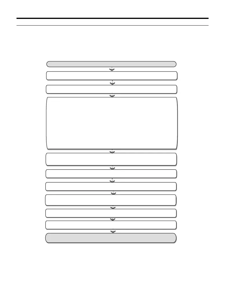
◆ Flowchart D: Permanent Magnet Motor Control (PM)
Figure 4.9 illustrates PM Open Loop Vector Control setup procedures, which
utilizes energy saving functions for reduced or variable torque loads.
Figure 4. 9
Figure 4.9 PM OLV Control
Set A1-02=5 for PM Open Loop Vector Control
START
Set the parameters C2-01 and n8-51.
Set the load inertia (n8-55) to match the connected machinery.
Adjust and fine-tune parameter settings.
The drive is ready to run the application.
Enter the motor code to E5-01 for the motor being used.
Run the motor without load, check the operation and verify, external
signal commands to the drive work as desired.
Couple the load or machine to the motor. Run the drive and motor
and check direction and operation
Check system operation and verify settings function as required.
Use parameter A1-06 (application selection) for basic application
setup
OR
manually set/check the basic parameters:
* b1-01, b1-02 for frequency reference and run command source
* H1-xx, H2-xx, H3-xx, H4-xx, H6-xx to configure the analog/digital
I/O terminals.
* d1-xx speed reference values if necessary
* C1-xx, C2-xx for Acceleration/Deceleration times and S-curves
* C6-01 Duty Mode

 Loading...


