4.4 Basic Parameter Adjustments
YASKAWA TM.V1000.01 V1000 Drive Installation & Start-Up Manual (Preliminary 01-19-07) 153
Start-Up Programming &
Operation
4
◆ Analog Outputs: H4-01 to H4-03
Group U parameters can be used to observe the drive status (operating conditions)
through the LED operator. Analog outputs corresponding to these monitors can be
obtained on analog output terminal AM or Fm when programmed with parameter
group H4. Some Group U monitors are not available as analog outputs.
■ Changing Analog Output Settings
The following example illustrates how to program analog output terminal FM to
generate a signal proportional to drive output current (monitor U1-03).
Using H4-01 to Display Monitor Contents
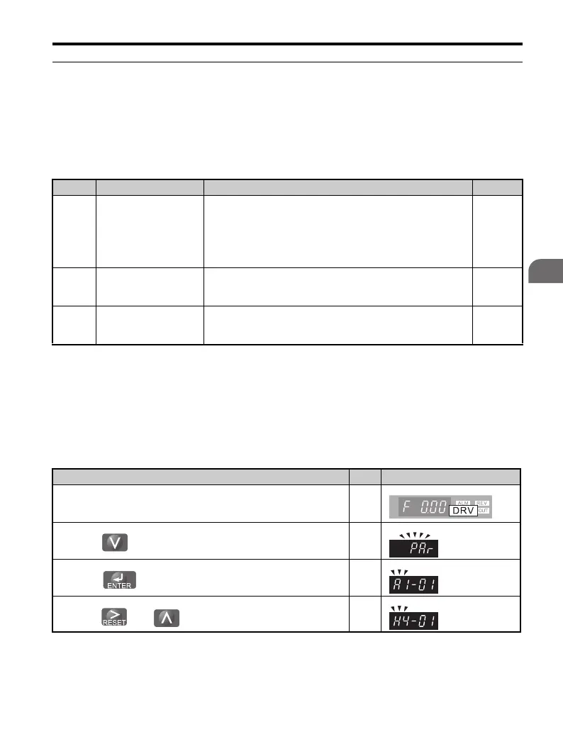
No. Parameter Name Description Page
H4-01
Multi-Function Analog 1
(Terminal AM Monitor
Selection)
Select the data to be output through multi-function analog output
terminal AM.
Set the desired monitor parameter to the digits available in
U1-. For example, enter “103” for U1-03.
When using this terminal as a through terminal or when not using
it at all, set “000” or “031”.
—
H4-02
<1>
<1> Indicates that the parameter can be changed during run.
Multi-Function Analog 1
(Terminal AM Output
Gain)
Sets terminal AM output level when selected monitor is at 100%.
Maximum output voltage is 10 V (can be adjusted with a
voltmeter).
—
H4-03
<1>
Terminal AM Bias
Setting
Sets the voltage level bias for terminal AM.
The bias added is 0 to ±10% with a maximum voltage output of
10 V as 100%.
—
Step Display/Result
1. Turn on the power to the drive. The initial display appears. ⇒
2.
Press until the Parameter setting menu is displayed.
⇒
3.
Press to enter the Parameter setting menu.
⇒
4.
Press and to select H4-01.
⇒

 Loading...


