YASKAWA TM.V1000.01 V1000 Drive Installation & Start-Up Manual (Preliminary 01-19-07) 27
1.4 Component Names
Receiving
1
1.4 Component Names
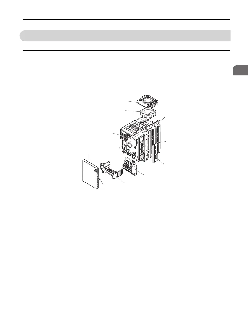
◆ IP20/Open-Chassis
■ Single-phase 200 Vac Models:
CIMR-VBA0001A to CIMR-VBA0003A
Three-phase 200 Vac Models:
CIMR-V2A0001A to CIMR-V2A0006A
Figure 1.2
Figure 1.2 Exploded View of IP20/Open-Chassis Type Components
Three-Phase 200 Vac Model CIMR-V2A0006A
A – Fan cover G – Front cover screw
B – Mounting hole H – Front cover
C – Heatsink I – Comm port
Refer to Network
Communications on page 427
D – Optional 24 V DC power
supply connector cover
J – LED operator
Refer to Using the Digital LED
Operator on page 102
E – Terminal board
Refer to Table 3.6 on page 77
K – Cooling fan
Refer to Drive Cooling Fans on
page 278
F – Terminal cover
A
B
C
D
E
F
G
H
I
J
K

 Loading...


