B.2 Parameter Table
408 YASKAWA TM.V1000.01 V1000 Drive Installation & Start-Up Manual (Preliminary 01-19-07)
◆ U: Monitors
Monitor parameters allow the user to view drive performance and other
information about drive operation.
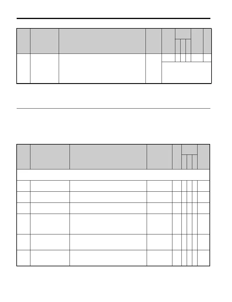
T1-11
Motor Iron
Loss
Provides the iron loss for determining the Energy
Saving coefficient.
When power is cycled, the value set to E2-10 will
appear (the motor iron loss). If T1-02 is changed,
an initial value for the motor capacity will appear
that is close to the capacity that was changed.
0 to
65535
14W A −− 70B —
These values differ
depending on the motor
code value and motor
parameter settings.
<12> Default setting value is dependent on parameter o2-04, Drive/kVA Selection.
<24> Values shown here are for 200 V class drives. Double the value when using a 400 V class drive.
<41> If T1-01 = 2, then T1-02 and T1-04 must also be set.
No. Name Description Range Def.
Control
Mode
Addr.
Hex
V/
f
O
L
V
P
M
U1: Operation Status Monitors
Use U1 monitors to display the operation status of the drive.
U1-01 Frequency Reference
Monitors the frequency reference in Remote
mode.
10 V: Max
frequency
0.01
Hz
AAA 40
U1-02 Output Frequency
Displays the output voltage. Display units are
determined by o1-03.
10 V: Max
frequency
0.01
Hz
AAA 41
U1-03 Output Current Displays the output current.
10 V: Drive
rated current
0.01
A
AAA 42
U1-04 Control Mode
Control method set in A1-02.
0: V/f without PG
2: Open Loop Vector (OLV)
5: PM Open Loop Vector (PM)
No output
signal
available
–AAA43
U1-05 Motor Speed
Displays the motor speed feedback.
Display units are determined by o1-03.
10 V:
Maximum
speed
0.01
Hz
–AA 44
U1-06
Output Voltage
Reference
Displays the output voltage.
10 V: 200
Vrms
(400 Vrms)
0.1
V
AAA 45
No. Name Description Range Def.
Control
Mode
Addr.
Hex
Pg.
V/
f
O
L
V
P
M

 Loading...


