294 YASKAWA TM.V1000.01 V1000 Drive Installation & Start-Up Manual (Preliminary 01-19-07)
7.3 Connecting Peripheral Devices
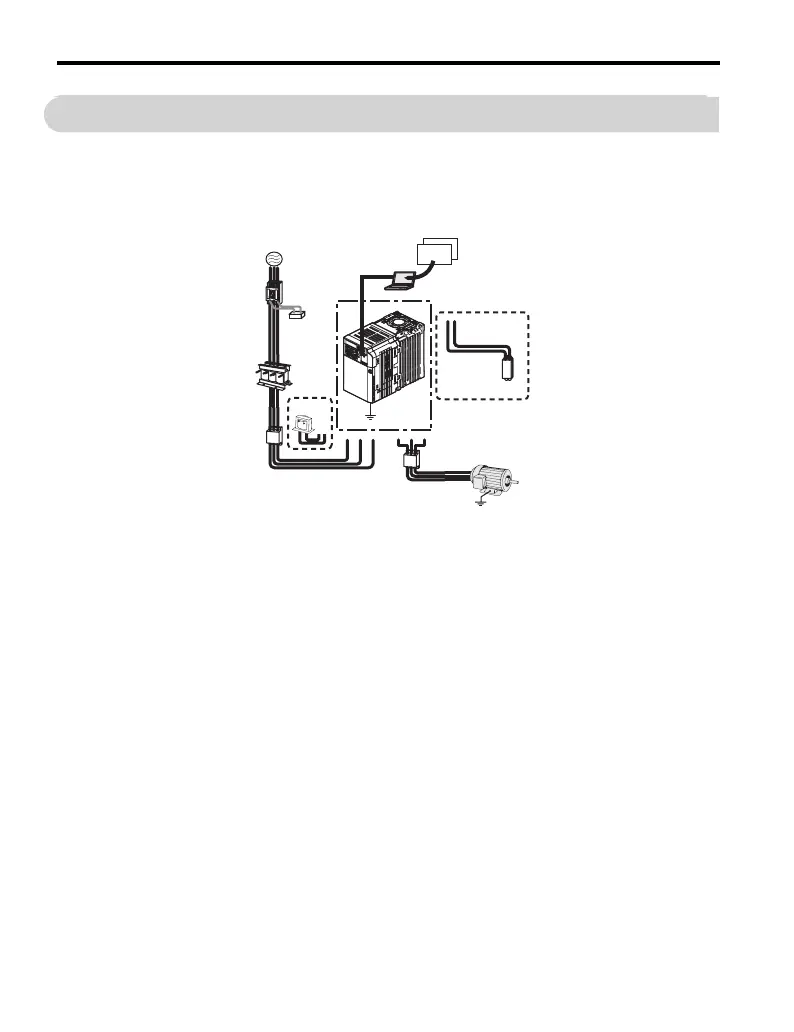
7.3 Connecting Peripheral Devices
Figure 7.1 illustrates how the drive and motor connect together with various
peripheral devices.
• Refer to peripheral device option manual for detailed installation instructions.
Figure 7. 1
Figure 7.1 Connecting Peripheral Devices
A – Engineering
software tools
H – unused O – Ground
B – unused I – unused P – Drive
C – unused J – unused Q – Surge protector
D – Braking
Resistor Unit or
braking resistor
K – Input-side
noise filter
(contact
Yaskawa)
R – unused
E–Output-side
noise filter
(contact
Yaskawa)
L – unused S – Line breaker
(MCCB) or
leakage breaker
F – Motor M – DC reactor T – unused
G – Ground N – AC reactor U – To V1000 serial
communication
port
V – unused
P
O
PC
G
F
A
U/T1 V/T2 W/T3R/L1 S/L2
+2+1
T/L3
DriveWizard
DriveWorksEZ
B1 B2
D
E
M
K
N
Q
S
T
U

 Loading...


