B.2 Parameter Table
YASKAWA TM.V1000.01 V1000 Drive Installation & Start-Up Manual (Preliminary 01-19-07) 421
Parameter List
B
◆ Default Settings Determined by Drive Capacity (o2-04)
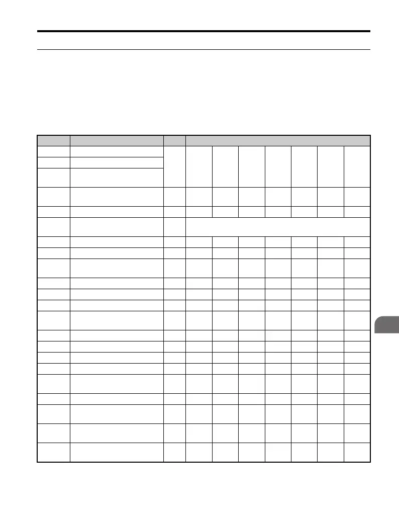
Default settings for the following parameters will vary based on drive capacity.
■ Single-Phase 200V Class
Table B.1 Default Settings Determined by Drive Capacity (o2-04):
Single-Phase, 200 V Class
No. Name Units Factory Default Value
– Drive Capacity
kW 0.1 0.2 0.4 0.75 1.5 2.2 3.7
E2-11 Motor Rated Capacity
E4-11
Motor Rated Capacity for
Motor 2
o2-04 Drive Capacity Selection –
48
(30H)
49
(31H)
50
(32H)
51
(33H)
52
(34H)
53
(35H)
55
(37H)
b3-04 V/f during Speed Search % 100 100 100 100 100 100 100
b8-03
Energy Control Carrier Time
Constant
s 0.50 (Open Loop Vector)
b8-04 Energy Saving Coefficient – 481.7 356.9 288.2 223.7 169.4 156.8 122.9
C6-02 Carrier Frequency Selection kHz 10 10 10 10 8 8 8
–
Carrier Frequency Selection
Upper Limit
kHz15151515151515
E2-01 Motor Rated Current A 0.6 1.1 1.9 3.3 6.2 8.5 14
E2-02 Motor Rated Slip Hz 2.5 2.6 2.9 2.5 2.6 2.9 2.73
E2-03 Motor No-Load Current A 0.4 0.8 1.2 1.8 2.8 3 4.5
E2-05
Motor Resistance Between
Lines
Ω 35.98 20.56 9.842 5.156 1.997 1.601 0.771
E2-06 Motor Leakage Inductance % 21.6 20.1 18.2 13.8 18.5 18.4 19.6
E2-10 Motor 2 Rated Current W 6 11 14 26 53 77 112
E4-01 Motor 2 Rated Slip A 0.6 1.1 1.9 3.3 6.2 8.5 14
E4-02 Motor 2 No-Load Current Hz 2.5 2.6 2.9 2.5 2.6 2.9 2.73
E4-03
Motor 2 Line-to-Line
Resistance
A 0.4 0.8 1.2 1.8 2.8 3 4.5
E4-05 Motor 2 Leakage Inductance Ω 35.98 20.56 9.842 5.156 1.997 1.601 0.771
E4-06
Torque Compensation Motor
Iron Loss
% 21.6 20.1 18.2 13.8 18.5 18.4 19.6
n1-03
Hunting Prevention Time
Constant
ms 10 10 10 10 10 10 10
L2-02
Momentary Power Loss
Ride-thru Time
s 0.1 0.1 0.1 0.2 0.3 0.5 1

 Loading...


